HP Xw460c Hardware and Software Supported by HP ProLiant Blade Workstations - - Page 23
PCIe card, retainer clip
 |
View all HP Xw460c manuals
Add to My Manuals
Save this manual to your list of manuals |
Page 23 highlights
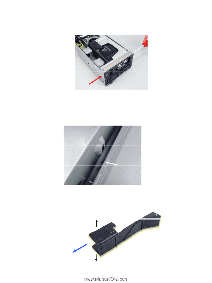
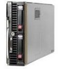
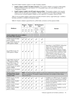
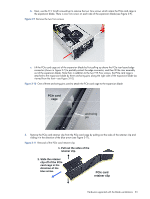
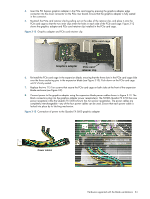
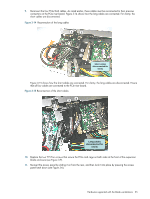
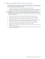
b. Next, use the T15 Torx® screwdriver to remove the two Torx screws which retain the PCIe card cage in the expansion blade. There is one Torx screw on each side of the expansion blade (see Figure 3-9). Figure 3-9 Remove the two Torx screws c. Lift the PCIe card cage out of the expansion blade by first pulling up above the PCIe riser board edge connector (shown in Figure 3-7) to partially extract the edge connector, and then lift the riser assembly out of the expansion blade. Note that, in addition to the two T15 Torx screws, the PCIe card cage is attached to the expansion blade by three anchoring pins along the right side of the expansion blade (as viewed from the front-see Figure 3-10). Figure 3-10 One of three anchoring pins used to attach the PCIe card cage to the expansion blade PCIe card cage anchoring pin 3. Remove the PCIe card retainer clip from the PCIe card cage by pulling out the sides of the retainer clip and sliding it in the direction of the blue arrow (see Figure 3-11). Figure 3-11 Removal of the PCIe card retainer clip 1. Pull out the sides of the retainer clip. 2. Slide the retainer clip off of the PCIe card cage in the direction of the blue arrow. PCIe card retainer clip Hardware supported with the blade workstations 23
-
 1
1 -
2
-
3
-
4
-
5
-
6
-
7
-
8
-
9
-
10
-
11
-
12
-
13
-
14
-
15
-
16
-
17
-
 18
18 -
 19
19 -
 20
20 -
 21
21 -
 22
22 -
 23
23 -
 24
24 -
 25
25 -
 26
26 -
 27
27 -
 28
28 -
29
-
30
-
31
-
32
-
33
-
34
-
35
 |
 |