HP Xw460c Hardware and Software Supported by HP ProLiant Blade Workstations - - Page 26
Removing a graphics adapter from the expansion blade
 |
View all HP Xw460c manuals
Add to My Manuals
Save this manual to your list of manuals |
Page 26 highlights
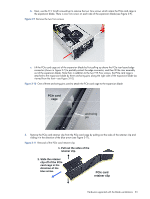
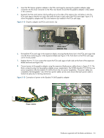
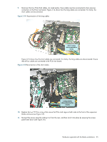
3-6-4 Removing a graphics adapter from the expansion blade This section describes how to remove a graphics adapter from the expansion blade. In many cases, the steps are identical to the steps to add a graphics adapter-in such cases, steps in the previous section are referenced. To remove a graphics adapter, perform the following steps: 1. Follow Step 1 in the previous section to remove the expansion blade access panel. 2. Disconnect the graphics adapter power cable(s) by pressing the release mechanism above each power cable connector and pulling the connector out of the graphics adapter power receptacle (see Figure 3-13). IMPORTANT: In the next step, the four PCIe/SAS cables are disconnected. These cables will need to be reconnected to their same connectors on the PCIe riser board, as described in Step 8 below. Their locations should be noted to ensure that each cable can be reconnected to the same connector on the PCIe riser board that it was disconnected from. 3. Follow Step 2 in the previous section to remove the PCIe card cage from the expansion blade. 4. Follow Step 3 in the previous section to remove the PCIe card retainer clip from the PCIe card cage. 5. Pull the graphics board out of the slot on the PCIe riser board and remove it from the card cage. 6. Re-attach the PCIe card retainer clip by pulling out on the sides of the retainer clip, and place it onto the PCIe card cage so that the two inner clips enter the holes in each side of the PCIe card cage. 7. Re-install the PCIe card cage in the expansion blade as described in Step 6 of the previous section. 8. Reconnect the four PCIe/SAS cables as described in Step 9 of the previous section. 9. Replace the two T15 Torx screws that secure the PCIe card cage on both sides at the front of the expansion blade enclosure (see Figure 3-9). 10. Re-insert the access panel by sliding it on from the rear, and then lock it into place by pressing the access panel latch down (see Figure 3-6). Hardware supported with the blade workstations 26
-
 1
1 -
2
-
3
-
4
-
5
-
6
-
7
-
8
-
9
-
10
-
11
-
12
-
13
-
14
-
15
-
16
-
17
-
18
-
19
-
20
-
 21
21 -
 22
22 -
 23
23 -
 24
24 -
 25
25 -
 26
26 -
 27
27 -
 28
28 -
 29
29 -
 30
30 -
 31
31 -
32
-
33
-
34
-
35
 |
 |