HP dx2700 Service Reference Guide: HP Compaq dx2700 MT/dx2708 MT/dx2700 SFF Bu - Page 40
Front Bezel MT Chassis, Preparation for Disassembly, Access Panel MT Chassis
 |
View all HP dx2700 manuals
Add to My Manuals
Save this manual to your list of manuals |
Page 40 highlights
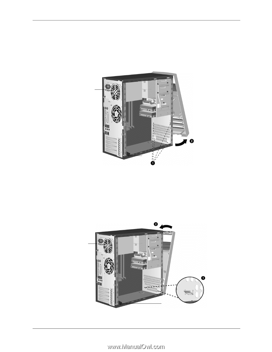
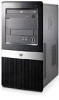
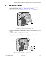
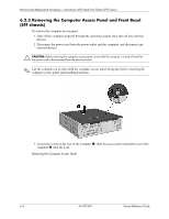
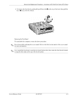
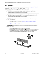
Removal and Replacement Procedures- Microtower (MT)/Small Form Factor (SFF) Chassis 6.2.2 Front Bezel (MT Chassis) 1. Prepare the computer for disassembly (Section 6.1, "Preparation for Disassembly"). 2. Remove the access panel (Section 6.2.1, "Access Panel (MT Chassis)"). 3. Press down on all four tabs on the bottom of bezel then rotate the bezel off the chassis. * * * These apply for selected models and countries only. 4. Continue to rotate the bezel, then push the bezel to the bottom to release the top latches from chassis. To reinstall the front bezel, reverse the removal procedure. 5. Position the chassis in the upright position. Insert the four tabs at the bottom of the bezel. Snap into the slots of the chassis. Align the two hooks on the top of the bezel into the rectangular holes on the chassis, then rotate the bezel into the place. * * * These apply for selected models and countries only. Service Reference Guide 431672-001 6-3
-
 1
1 -
2
-
3
-
4
-
5
-
6
-
7
-
8
-
9
-
10
-
11
-
12
-
13
-
14
-
15
-
16
-
17
-
18
-
19
-
20
-
21
-
22
-
23
-
24
-
25
-
26
-
27
-
28
-
29
-
30
-
31
-
32
-
33
-
34
-
 35
35 -
 36
36 -
 37
37 -
 38
38 -
 39
39 -
 40
40 -
 41
41 -
 42
42 -
 43
43 -
 44
44 -
 45
45 -
46
-
47
-
48
-
49
-
50
-
51
-
52
-
53
-
54
-
55
-
56
-
57
-
58
-
59
-
60
-
61
-
62
-
63
-
64
-
65
-
66
-
67
-
68
-
69
-
70
-
71
-
72
-
73
-
74
-
75
-
76
-
77
-
78
-
79
-
80
-
81
-
82
-
83
-
84
-
85
-
86
-
87
-
88
-
89
-
90
-
91
-
92
-
93
-
94
-
95
-
96
-
97
-
98
-
99
-
100
-
101
-
102
-
103
-
104
-
105
-
106
-
107
 |
 |