HP dx2700 Service Reference Guide: HP Compaq dx2700 MT/dx2708 MT/dx2700 SFF Bu - Page 45
Memory, 5.1 Installing Memory Modules/MT chassis
 |
View all HP dx2700 manuals
Add to My Manuals
Save this manual to your list of manuals |
Page 45 highlights
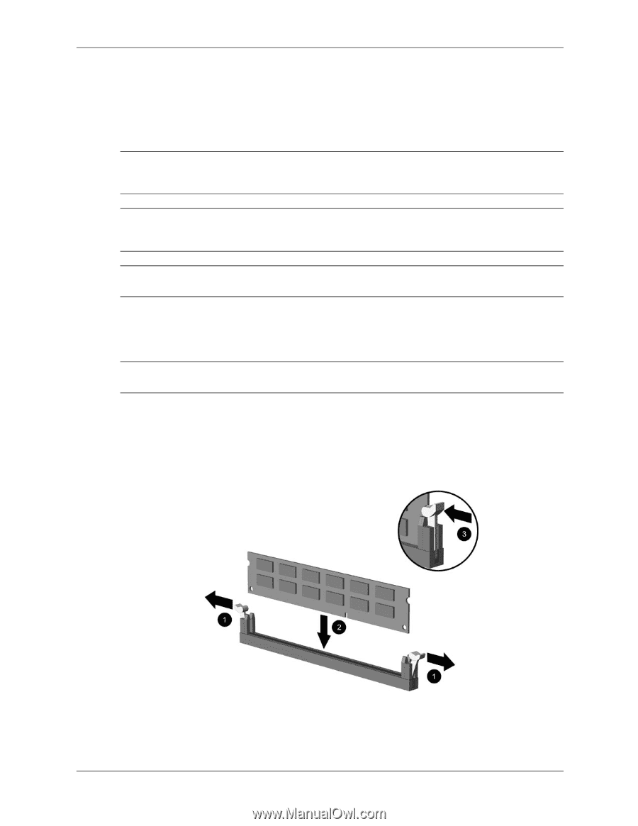
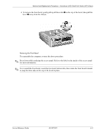
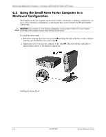
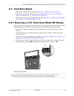
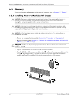
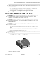
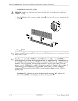
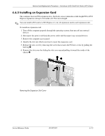
Removal and Replacement Procedures- Microtower (MT)/Small Form Factor (SFF) Chassis 6.5 Memory For more information on the memory in this series of computers, refer to Appendix E, "Memory." 6.5.1 Installing Memory Modules/MT chassis Ä CAUTION: The memory module sockets have gold metal contacts. When upgrading the memory, it is important to use memory modules with gold metal contacts to prevent corrosion and/or oxidation resulting from having incompatible metals in contact with each other. Ä CAUTION: Static electricity can damage the electronic components of the computer or optional cards. Before beginning these procedures, ensure that you are discharged of static electricity by briefly touching a grounded metal object. Refer to Chapter 5 for more information. Ä CAUTION: When handling a memory module, be careful not to touch any of the contacts. Doing so may damage the module. 1. Prepare the computer for disassembly (Section 6.1, "Preparation for Disassembly"). 2. Remove the access panel (Section 6.2, "Remove the computer access panel and front bezel (MT chassis and SFF chassis)"). Å WARNING: To reduce risk of personal injury from hot surfaces, allow the internal system components to cool before touching. 3. Lay the computer down on its side to make it easier to work on. 4. Open both latches of the memory module socket 1, and insert the memory module into the socket 2. Begin by installing a module into the socket second nearest the preinstalled module, and install the modules following the numerical order of the sockets. 6-8 431672-001 Service Reference Guide
-
 1
1 -
2
-
3
-
4
-
5
-
6
-
7
-
8
-
9
-
10
-
11
-
12
-
13
-
14
-
15
-
16
-
17
-
18
-
19
-
20
-
21
-
22
-
23
-
24
-
25
-
26
-
27
-
28
-
29
-
30
-
31
-
32
-
33
-
34
-
35
-
36
-
37
-
38
-
39
-
 40
40 -
 41
41 -
 42
42 -
 43
43 -
 44
44 -
 45
45 -
 46
46 -
 47
47 -
 48
48 -
 49
49 -
 50
50 -
51
-
52
-
53
-
54
-
55
-
56
-
57
-
58
-
59
-
60
-
61
-
62
-
63
-
64
-
65
-
66
-
67
-
68
-
69
-
70
-
71
-
72
-
73
-
74
-
75
-
76
-
77
-
78
-
79
-
80
-
81
-
82
-
83
-
84
-
85
-
86
-
87
-
88
-
89
-
90
-
91
-
92
-
93
-
94
-
95
-
96
-
97
-
98
-
99
-
100
-
101
-
102
-
103
-
104
-
105
-
106
-
107
 |
 |