HP dx2700 Service Reference Guide: HP Compaq dx2700 MT/dx2708 MT/dx2700 SFF Bu - Page 66
Processor, Heatsink - MT chassis
 |
View all HP dx2700 manuals
Add to My Manuals
Save this manual to your list of manuals |
Page 66 highlights
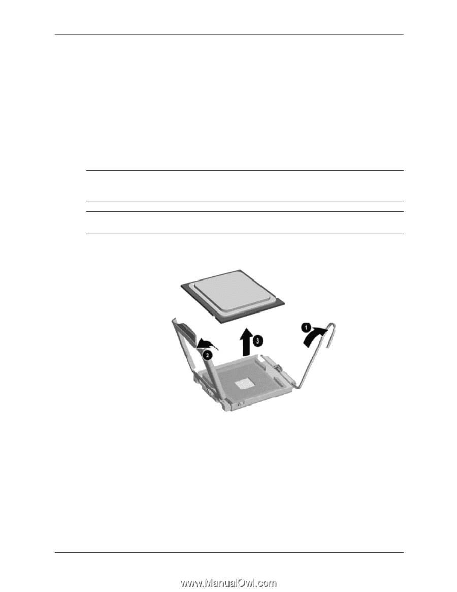
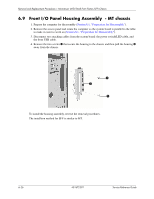
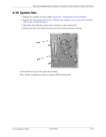
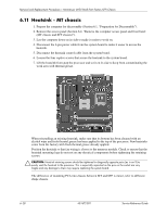
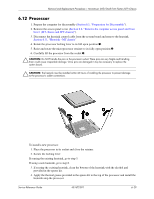
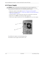
Removal and Replacement Procedures- Microtower (MT)/Small Form Factor (SFF) Chassis 6.12 Processor 1. Prepare the computer for disassembly (Section 6.1, "Preparation for Disassembly"). 2. Remove the access panel cover (Section 6.2, "Remove the computer access panel and front bezel (MT chassis and SFF chassis)"). 3. Disconnect the heatsink control cable from the system board and remove the heatsink. Section 6.11, "Heatsink - MT chassis" 4. Rotate the processor locking lever to its full open position 1. 5. Raise and rotate the microprocessor retainer to its fully open position 2. 6. Carefully lift the processor from the socket 3. Ä CAUTION: Do NOT handle the pins in the processor socket. These pins are very fragile and handling them could cause irreparable damage. Once pins are damaged it may be necessary to replace the system board. Ä CAUTION: The heatsink must be installed within 24 hours of installing the processor to prevent damage to the processor's solder connections. To install a new processor: 1. Place the processor in its socket and close the retainer. 2. Secure the locking lever. If reusing the existing heatsink, go to step 3. If using a new heatsink, go to step 6. 3. If reusing the existing heatsink, clean the bottom of the heatsink with the alcohol pad provided in the spares kit. 4. Apply the thermal grease provided in the spares kit to the top of the processor and install the heatsink atop the processor. Service Reference Guide 431672-001 6-29
-
 1
1 -
2
-
3
-
4
-
5
-
6
-
7
-
8
-
9
-
10
-
11
-
12
-
13
-
14
-
15
-
16
-
17
-
18
-
19
-
20
-
21
-
22
-
23
-
24
-
25
-
26
-
27
-
28
-
29
-
30
-
31
-
32
-
33
-
34
-
35
-
36
-
37
-
38
-
39
-
40
-
41
-
42
-
43
-
44
-
45
-
46
-
47
-
48
-
49
-
50
-
51
-
52
-
53
-
54
-
55
-
56
-
57
-
58
-
59
-
60
-
 61
61 -
 62
62 -
 63
63 -
 64
64 -
 65
65 -
 66
66 -
 67
67 -
 68
68 -
 69
69 -
 70
70 -
 71
71 -
72
-
73
-
74
-
75
-
76
-
77
-
78
-
79
-
80
-
81
-
82
-
83
-
84
-
85
-
86
-
87
-
88
-
89
-
90
-
91
-
92
-
93
-
94
-
95
-
96
-
97
-
98
-
99
-
100
-
101
-
102
-
103
-
104
-
105
-
106
-
107
 |
 |