HP dx2700 Service Reference Guide: HP Compaq dx2700 MT/dx2708 MT/dx2700 SFF Bu - Page 63
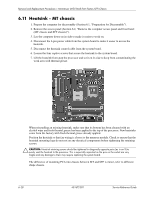
Front I/O Panel Housing Assembly - MT chassis, Preparation for Disassembly
 |
View all HP dx2700 manuals
Add to My Manuals
Save this manual to your list of manuals |
Page 63 highlights
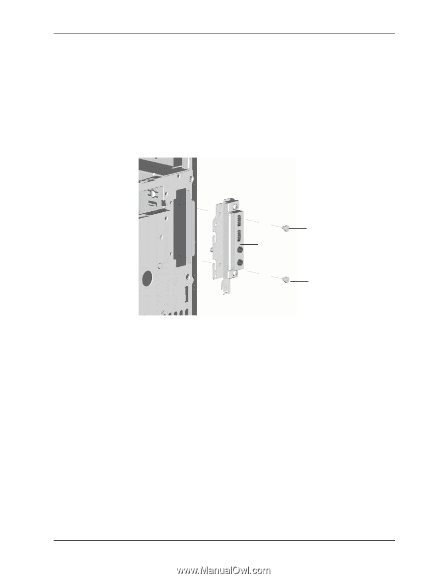
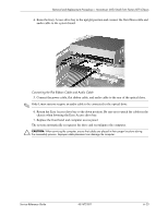
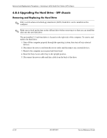
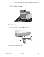
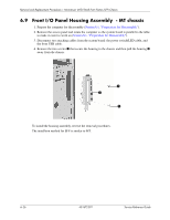
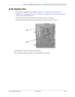
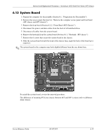
Removal and Replacement Procedures- Microtower (MT)/Small Form Factor (SFF) Chassis 6.9 Front I/O Panel Housing Assembly - MT chassis 1. Prepare the computer for disassembly (Section 6.1, "Preparation for Disassembly"). 2. Remove the access panel and rotate the computer so the system board is parallel to the table to make it easier to work on (Section 6.1, "Preparation for Disassembly"). 3. Disconnect two attaching cables from the system board: the power switch/LED cable, and the front USB cable. 4. Remove the two screws 1 that secure the housing to the chassis and then pull the housing 2 away from the chassis. 1 2 1 To install the housing assembly, reverse the removal procedures. The installtion method for SFF is similar to MT. 6-26 431672-001 Service Reference Guide
-
 1
1 -
2
-
3
-
4
-
5
-
6
-
7
-
8
-
9
-
10
-
11
-
12
-
13
-
14
-
15
-
16
-
17
-
18
-
19
-
20
-
21
-
22
-
23
-
24
-
25
-
26
-
27
-
28
-
29
-
30
-
31
-
32
-
33
-
34
-
35
-
36
-
37
-
38
-
39
-
40
-
41
-
42
-
43
-
44
-
45
-
46
-
47
-
48
-
49
-
50
-
51
-
52
-
53
-
54
-
55
-
56
-
57
-
 58
58 -
 59
59 -
 60
60 -
 61
61 -
 62
62 -
 63
63 -
 64
64 -
 65
65 -
 66
66 -
 67
67 -
 68
68 -
69
-
70
-
71
-
72
-
73
-
74
-
75
-
76
-
77
-
78
-
79
-
80
-
81
-
82
-
83
-
84
-
85
-
86
-
87
-
88
-
89
-
90
-
91
-
92
-
93
-
94
-
95
-
96
-
97
-
98
-
99
-
100
-
101
-
102
-
103
-
104
-
105
-
106
-
107
 |
 |