HP dx2700 Service Reference Guide: HP Compaq dx2700 MT/dx2708 MT/dx2700 SFF Bu - Page 65
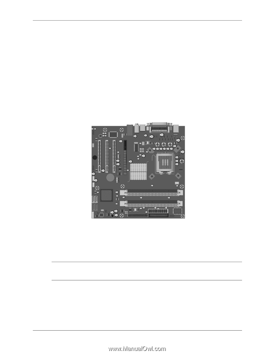
Heatsink - MT chassis, come from the factory with fresh thermal grease already applied.
 |
View all HP dx2700 manuals
Add to My Manuals
Save this manual to your list of manuals |
Page 65 highlights
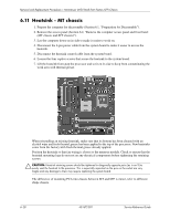
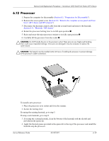
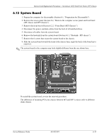
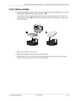
Removal and Replacement Procedures- Microtower (MT)/Small Form Factor (SFF) Chassis 6.11 Heatsink - MT chassis 1. Prepare the computer for disassembly (Section 6.1, "Preparation for Disassembly"). 2. Remove the access panel (Section 6.2, "Remove the computer access panel and front bezel (MT chassis and SFF chassis)"). 3. Lay the computer down on its side to make it easier to work on. 4. Disconnect the 4-pin power cable from the system board to make it easier to access the heatsink. 5. Disconnect the heatsink control cable from the system board. 6. Loosen the four captive screws that secure the heatsink to the system board. 7. Lift the heatsink from atop the processor and set it on its side to keep from contaminating the work area with thermal grease. When reinstalling an existing heatsink, make sure that its bottom has been cleaned with an alcohol wipe and fresh thermal grease has been applied to the top of the processor. New heatsinks come from the factory with fresh thermal grease already applied. Position the heatsink so that fan wiring is closest to the memory module. Check to ensure that the heatsink mounting lugs do not rest on any electrical components before tightening the retaining screws. Ä CAUTION: Heatsink retaining screws should be tightened in diagonally opposite pairs (as in an X) to evenly seat the heatsink to the processor. This is especially important as the pins on the socket are very fragile and any damage to them may require replacing the system board. The difference of mounting PCA into chassis between MT and SFF is minor, refer to different shape chassis. 6-28 431672-001 Service Reference Guide
-
 1
1 -
2
-
3
-
4
-
5
-
6
-
7
-
8
-
9
-
10
-
11
-
12
-
13
-
14
-
15
-
16
-
17
-
18
-
19
-
20
-
21
-
22
-
23
-
24
-
25
-
26
-
27
-
28
-
29
-
30
-
31
-
32
-
33
-
34
-
35
-
36
-
37
-
38
-
39
-
40
-
41
-
42
-
43
-
44
-
45
-
46
-
47
-
48
-
49
-
50
-
51
-
52
-
53
-
54
-
55
-
56
-
57
-
58
-
59
-
 60
60 -
 61
61 -
 62
62 -
 63
63 -
 64
64 -
 65
65 -
 66
66 -
 67
67 -
 68
68 -
 69
69 -
 70
70 -
71
-
72
-
73
-
74
-
75
-
76
-
77
-
78
-
79
-
80
-
81
-
82
-
83
-
84
-
85
-
86
-
87
-
88
-
89
-
90
-
91
-
92
-
93
-
94
-
95
-
96
-
97
-
98
-
99
-
100
-
101
-
102
-
103
-
104
-
105
-
106
-
107
 |
 |