HP dx2700 Service Reference Guide: HP Compaq dx2700 MT/dx2708 MT/dx2700 SFF Bu - Page 46
Installing DDR2-SDRAM DIMMs, SFF chassis
 |
View all HP dx2700 manuals
Add to My Manuals
Save this manual to your list of manuals |
Page 46 highlights
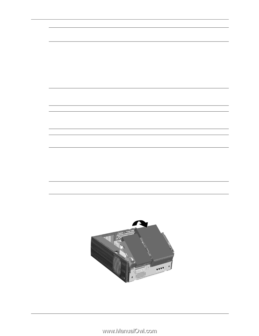
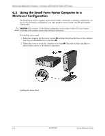
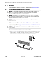
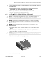
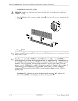
Removal and Replacement Procedures- Microtower (MT)/Small Form Factor (SFF) Chassis ✎ A memory module can be installed in only one way. Match the notch on the module with the tab on the memory socket. 5. Push the module down into the socket, ensuring that the module is fully inserted and properly seated. Make sure the latches are in the closed position 3. 6. Repeat steps 4 and 5 for any additional modules that you want to install. To reassemble the computer, reverse the removal procedure. 6.5.2 Installing DDR2-SDRAM DIMMs - SFF chassis Ä CAUTION: The memory module sockets have gold metal contacts. When upgrading the memory, it is important to use memory modules with gold metal contacts to prevent corrosion and/or oxidation resulting from having incompatible metals in contact with each other. Ä CAUTION: Static electricity can damage the electronic components of the computer or optional cards. Before beginning these procedures, ensure that you are discharged of static electricity by briefly touching a grounded metal object. Ä CAUTION: When handling a memory module, be careful not to touch any of the contacts. Doing so may damage the module. 1. Turn off the computer properly through the operating system, then turn off any external devices. 2. Disconnect the power cord from the power outlet and disconnect any external devices. 3. Remove the computer access panel and front bezel. Ä CAUTION: Check the position of all cables and wires before raising or lowering the Easy Access drive bay to prevent damage. 4. Rotate the Easy Access drive bay to an upright position. Rotating the Easy Access Drive Bay Service Reference Guide 431672-001 6-9
-
 1
1 -
2
-
3
-
4
-
5
-
6
-
7
-
8
-
9
-
10
-
11
-
12
-
13
-
14
-
15
-
16
-
17
-
18
-
19
-
20
-
21
-
22
-
23
-
24
-
25
-
26
-
27
-
28
-
29
-
30
-
31
-
32
-
33
-
34
-
35
-
36
-
37
-
38
-
39
-
40
-
 41
41 -
 42
42 -
 43
43 -
 44
44 -
 45
45 -
 46
46 -
 47
47 -
 48
48 -
 49
49 -
 50
50 -
 51
51 -
52
-
53
-
54
-
55
-
56
-
57
-
58
-
59
-
60
-
61
-
62
-
63
-
64
-
65
-
66
-
67
-
68
-
69
-
70
-
71
-
72
-
73
-
74
-
75
-
76
-
77
-
78
-
79
-
80
-
81
-
82
-
83
-
84
-
85
-
86
-
87
-
88
-
89
-
90
-
91
-
92
-
93
-
94
-
95
-
96
-
97
-
98
-
99
-
100
-
101
-
102
-
103
-
104
-
105
-
106
-
107
 |
 |