Hitachi IC25N040ATCS04-0 Specifications - Page 10

Hitachi IC25N040ATCS04-0 - Travelstar 40GN 40GB UDMA/100 4200RPM 2MB 2.5" IDE Hard Drive Manual

Page 10 highlights

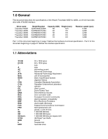
Figures Figure 1. Handling Precaution 1 3 Figure 2. Handling Precaution 2 3 Figure 3. Formatted capacity by model number 11 Figure 4. Data sheet 12 Figure 5. Cylinder allocation of 60 GB model 12 Figure 6. Cylinder allocation - all models except 60 GB (high TPI format 13 Figure 7. Cylinder allocation - all models except 60 GB (low TPI format 13 Figure 8. Performance characteristics 14 Figure 9. Mechanical positioning performance 15 Figure 10. Full stroke seek time 15 Figure 11. Single track seek time 16 Figure 12. Latency time 16 Figure 13. Drive ready time 16 Figure 14. Operating mode 17 Figure 15. Drive ready time 17 Figure 16. Examples of error cases 21 Figure 17. Environmental condition 23 Figure 18. Limits of temperature and humidity 23 Figure 19. Magnetic flux density limits 24 Figure 20. DC Power requirements 25 Figure 21. Power consumption efficiency 26 Figure 22. Typical current wave form at start up of 60 GB model 26 Figure 23. Typical current wave form at start up of 40 GB model 27 Figure 24. Typical current wave form at start up of 20 GB model 27 Figure 25. Physical dimensions and weight 31 Figure 26. Mounting hole locations of the 60 GB model 31 Figure 27. Mounting hole locations of all models except 60 GB model 32 Figure 28. Random vibration PSD profile breakpoints (operating 34 Figure 29. Swept sine vibration 34 Figure 30. Random Vibration PSD Profile Breakpoints (nonoperating 35 Figure 31. Operating shock 35 Figure 32. Nonoperating shock 36 Figure 33. Weighted sound power 37 Figure 34. Interface connector pin assignments 41 Figure 35. Signal definition 42 Figure 36. Special signal definitions for Ultra DMA 43 Figure 37. System reset timings 47 Figure 38. PIO cycle timings 48 Figure 39. Multiword DMA cycle timings 49 Figure 40. Ultra DMA cycle timings (Initiating Read 50 Figure 41. Ultra DMA cycle timings (Host Pausing Read 51 Figure 42. Ultra DMA cycle timings (Host Terminating Read 52 Figure 43. Ultra DMA cycle timings (Device Terminating Read 53 Figure 44. Ultra DMA cycle timings (Initiating Write 54 Figure 45. Ultra DMA cycle timings (Device Pausing Write 55 Figure 46. Ultra DMA cycle timings (Device Terminating Write 56 Figure 47. Ultra DMA cycle timings (Host Terminating Write 57 Figure 48. Drive address setting 58 Figure 49. I/O address map 59 Hitachi Travelstar 60GH & 40GN hard disk drive specifications ix

  • 1
  • 2
  • 3
  • 4
  • 5
  • 6
  • 7
  • 8
  • 9
  • 10
  • 11
  • 12
  • 13
  • 14
  • 15
  • 16
  • 17
  • 18
  • 19
  • 20
  • 21
  • 22
  • 23
  • 24
  • 25
  • 26
  • 27
  • 28
  • 29
  • 30
  • 31
  • 32
  • 33
  • 34
  • 35
  • 36
  • 37
  • 38
  • 39
  • 40
  • 41
  • 42
  • 43
  • 44
  • 45
  • 46
  • 47
  • 48
  • 49
  • 50
  • 51
  • 52
  • 53
  • 54
  • 55
  • 56
  • 57
  • 58
  • 59
  • 60
  • 61
  • 62
  • 63
  • 64
  • 65
  • 66
  • 67
  • 68
  • 69
  • 70
  • 71
  • 72
  • 73
  • 74
  • 75
  • 76
  • 77
  • 78
  • 79
  • 80
  • 81
  • 82
  • 83
  • 84
  • 85
  • 86
  • 87
  • 88
  • 89
  • 90
  • 91
  • 92
  • 93
  • 94
  • 95
  • 96
  • 97
  • 98
  • 99
  • 100
  • 101
  • 102
  • 103
  • 104
  • 105
  • 106
  • 107
  • 108
  • 109
  • 110
  • 111
  • 112
  • 113
  • 114
  • 115
  • 116
  • 117
  • 118
  • 119
  • 120
  • 121
  • 122
  • 123
  • 124
  • 125
  • 126
  • 127
  • 128
  • 129
  • 130
  • 131
  • 132
  • 133
  • 134
  • 135
  • 136
  • 137
  • 138
  • 139
  • 140
  • 141
  • 142
  • 143
  • 144
  • 145
  • 146
  • 147
  • 148
  • 149
  • 150
  • 151
  • 152
  • 153
  • 154
  • 155
  • 156
  • 157
  • 158
  • 159
  • 160
  • 161
  • 162
  • 163
  • 164
  • 165
  • 166
  • 167
  • 168
  • 169
  • 170
  • 171
  • 172
  • 173
  • 174
  • 175
  • 176
  • 177
  • 178
  • 179
  • 180
  • 181
  • 182
  • 183
  • 184
  • 185
  • 186
  • 187
  • 188
  • 189
  • 190
  • 191
  • 192
  • 193
  • 194
  • 195
  • 196
  • 197
  • 198
  • 199
  • 200
  • 201
  • 202
  • 203
  • 204
  • 205
  • 206
  • 207
  • 208
  • 209
  • 210
  • 211
  • 212
  • 213
  • 214
  • 215
  • 216
  • 217

Figures
59
Figure 49. I/O address map
................................................
58
Figure 48. Drive address setting
.............................................
57
Figure 47. Ultra DMA cycle timings (Host Terminating Write)
........................
56
Figure 46. Ultra DMA cycle timings (Device Terminating Write)
......................
55
Figure 45. Ultra DMA cycle timings (Device Pausing Write)
.........................
54
Figure 44. Ultra DMA cycle timings (Initiating Write)
..............................
53
Figure 43. Ultra DMA cycle timings (Device Terminating Read)
......................
52
Figure 42. Ultra DMA cycle timings (Host Terminating Read)
........................
51
Figure 41. Ultra DMA cycle timings (Host Pausing Read)
..........................
50
Figure 40. Ultra DMA cycle timings (Initiating Read)
..............................
49
Figure 39. Multiword DMA cycle timings
.......................................
48
Figure 38. PIO cycle timings
................................................
47
Figure 37. System reset timings
.............................................
43
Figure 36. Special signal definitions for Ultra DMA
...............................
42
Figure 35. Signal definition
.................................................
41
Figure 34. Interface connector pin assignments
.................................
37
Figure 33. Weighted sound power
............................................
36
Figure 32. Nonoperating shock
..............................................
35
Figure 31. Operating shock
.................................................
35
Figure 30. Random Vibration PSD Profile Breakpoints (nonoperating)
.................
34
Figure 29. Swept sine vibration
..............................................
34
Figure 28. Random vibration PSD profile breakpoints (operating)
....................
32
Figure 27. Mounting hole locations of all models except 60 GB model.
...............
31
Figure 26. Mounting hole locations of the 60 GB model.
..........................
31
Figure 25. Physical dimensions and weight
.....................................
27
Figure 24. Typical current wave form at start up of
20 GB model)
....................
27
Figure 23. Typical current wave form at start up of
40 GB model
....................
26
Figure 22. Typical current wave form at start up of 60 GB model
.....................
26
Figure 21. Power consumption efficiency
......................................
25
Figure 20. DC Power requirements
...........................................
24
Figure 19. Magnetic flux density limits
.........................................
23
Figure 18. Limits of temperature and humidity
...................................
23
Figure 17. Environmental condition
...........................................
21
Figure 16. Examples of error cases.
..........................................
17
Figure 15. Drive ready time
.................................................
17
Figure 14. Operating mode
.................................................
16
Figure 13. Drive ready time
.................................................
16
Figure 12. Latency time
...................................................
16
Figure 11. Single track seek time
............................................
15
Figure 10. Full stroke seek time
.............................................
15
Figure 9. Mechanical positioning performance
...................................
14
Figure 8. Performance characteristics
.........................................
13
Figure 7. Cylinder allocation — all models except 60 GB (low TPI format)
..............
13
Figure 6. Cylinder allocation — all models except 60 GB (high TPI format)
.............
12
Figure 5. Cylinder allocation of 60 GB model
....................................
12
Figure 4. Data sheet
......................................................
11
Figure 3. Formatted capacity by model number.
.................................
3
Figure 2. Handling Precaution 2
..............................................
3
Figure 1. Handling Precaution 1
..............................................
Hitachi Travelstar 60GH & 40GN hard disk drive specifications
ix