Hitachi IC25N040ATCS04-0 Specifications - Page 127
Error Information Example 2
 |
UPC - 683728198664
View all Hitachi IC25N040ATCS04-0 manuals
Add to My Manuals
Save this manual to your list of manuals |
Page 127 highlights
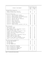
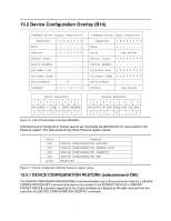
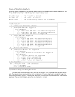
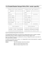
ERROR INFORMATION EXAMPLE 2: When the device is enabled and the Security feature is set, if the user attempts to disable that feature, the device aborts that command and returns an error reason code as below. Cylinder high : 07h = word 7 is invalid Cylinder low : 03h = bit 3 is invalid Sector count : 04h = now Security feature set is enabled Word Content 0 0001h Data Structure revision 1 Multiword DMA modes supported 15-3 Reserved 2 1 = Multiword DMA mode 2 and below are supported 1 1 = Multiword DMA mode 1 and below are supported 0 1 = Multiword DMA mode 0 is supported 2 Ultra DMA modes supported 15-6 Reserved 5 1 = Ultra DMA mode 5 and below are supported 4 1 = Ultra DMA mode 4 and below are supported 3 1 = Ultra DMA mode 3 and below are supported 2 1 = Ultra DMA mode 2 and below are supported 1 1 = Ultra DMA mode 1 and below are supported 0 1 = Ultra DMA mode 0 is supported 3-6 Maximum LBA address 7 Command set/feature set supported 15-8 Reserved 7 1 = Host Protected Area feature set supported 6-4 Reserved 3 1 = Security feature set supported 2 1 = SMART error log supported 1 1 = SMART self-test supported 0 1 = SMART feature set supported 8-254 Reserved 255 Integrity word 15-8 Checksum 7-0 Signature (A5h) Figure 78. Device Configuration Overlay Data structure Note: Bits 7-0 of this word contain the value A5h. Bits 15-8 of this word contain the data structure checksum. The data structure checksum is the two's complement of the sum of all byte in words 0 through 254 and the byte consisting of bits 7-0 of word 255. Each byte is added with unsigned arithmetic, and overflow is ignored. The sum of all bytes is zero when the checksum is correct. Hitachi Travelstar 60GH & 40GN hard disk drive specifications 114
-
 1
1 -
2
-
3
-
4
-
5
-
6
-
7
-
8
-
9
-
10
-
11
-
12
-
13
-
14
-
15
-
16
-
17
-
18
-
19
-
20
-
21
-
22
-
23
-
24
-
25
-
26
-
27
-
28
-
29
-
30
-
31
-
32
-
33
-
34
-
35
-
36
-
37
-
38
-
39
-
40
-
41
-
42
-
43
-
44
-
45
-
46
-
47
-
48
-
49
-
50
-
51
-
52
-
53
-
54
-
55
-
56
-
57
-
58
-
59
-
60
-
61
-
62
-
63
-
64
-
65
-
66
-
67
-
68
-
69
-
70
-
71
-
72
-
73
-
74
-
75
-
76
-
77
-
78
-
79
-
80
-
81
-
82
-
83
-
84
-
85
-
86
-
87
-
88
-
89
-
90
-
91
-
92
-
93
-
94
-
95
-
96
-
97
-
98
-
99
-
100
-
101
-
102
-
103
-
104
-
105
-
106
-
107
-
108
-
109
-
110
-
111
-
112
-
113
-
114
-
115
-
116
-
117
-
118
-
119
-
120
-
121
-
 122
122 -
 123
123 -
 124
124 -
 125
125 -
 126
126 -
 127
127 -
 128
128 -
 129
129 -
 130
130 -
 131
131 -
 132
132 -
133
-
134
-
135
-
136
-
137
-
138
-
139
-
140
-
141
-
142
-
143
-
144
-
145
-
146
-
147
-
148
-
149
-
150
-
151
-
152
-
153
-
154
-
155
-
156
-
157
-
158
-
159
-
160
-
161
-
162
-
163
-
164
-
165
-
166
-
167
-
168
-
169
-
170
-
171
-
172
-
173
-
174
-
175
-
176
-
177
-
178
-
179
-
180
-
181
-
182
-
183
-
184
-
185
-
186
-
187
-
188
-
189
-
190
-
191
-
192
-
193
-
194
-
195
-
196
-
197
-
198
-
199
-
200
-
201
-
202
-
203
-
204
-
205
-
206
-
207
-
208
-
209
-
210
-
211
-
212
-
213
-
214
-
215
-
216
-
217
 |
 |
