Hitachi IC25N040ATCS04-0 Specifications - Page 81
Alternate Status Register, 2 Command Register, 3 Cylinder High Register, 4 Cylinder Low Register
 |
UPC - 683728198664
View all Hitachi IC25N040ATCS04-0 manuals
Add to My Manuals
Save this manual to your list of manuals |
Page 81 highlights
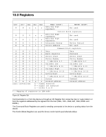
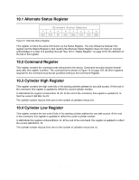
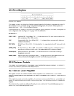
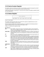
10.1 Alternate Status Register Alternate Status Register 7 6 5 4 3 2 1 0 BSY RDY DF DSC DRQ COR IDX ERR Figure 51. Alternate Status Register This register contains the same information as the Status Register. The only difference between this register and the Status Register is that reading the Alternate Status Register does not imply an interrupt acknowledge or a clear of a pending interrupt. See 10.13, "Status Register" on page 72 for the definition of the bits in this register. 10.2 Command Register This register contains the command code being sent to the device. Command execution begins immediately after this register is written. The command set is shown in Figure 72 on page 107. All other registers required for the command must be set up before writing to the Command Register. 10.3 Cylinder High Register This register contains the high order bits of the starting cylinder address for any disk access. At the end of the command, this register is updated to reflect the current cylinder number. In LBA Mode this register contains Bits 16-23. At the end of the command, this register is updated to reflect the current LBA Bits 16-23. The cylinder number may be from zero to the number of cylinders minus one. 10.4 Cylinder Low Register This register contains the low order 8 bits of the starting cylinder address for any disk access. At the end of the command, this register is updated to reflect the current cylinder number. In LBA Mode this register contains Bits 8-15. At the end of the command, this register is updated to reflect the current LBA Bits 8-15. The cylinder number may be from zero to the number of cylinders minus one (1). Hitachi Travelstar 60GH & 40GN hard disk drive specifications 68
-
 1
1 -
2
-
3
-
4
-
5
-
6
-
7
-
8
-
9
-
10
-
11
-
12
-
13
-
14
-
15
-
16
-
17
-
18
-
19
-
20
-
21
-
22
-
23
-
24
-
25
-
26
-
27
-
28
-
29
-
30
-
31
-
32
-
33
-
34
-
35
-
36
-
37
-
38
-
39
-
40
-
41
-
42
-
43
-
44
-
45
-
46
-
47
-
48
-
49
-
50
-
51
-
52
-
53
-
54
-
55
-
56
-
57
-
58
-
59
-
60
-
61
-
62
-
63
-
64
-
65
-
66
-
67
-
68
-
69
-
70
-
71
-
72
-
73
-
74
-
75
-
 76
76 -
 77
77 -
 78
78 -
 79
79 -
 80
80 -
 81
81 -
 82
82 -
 83
83 -
 84
84 -
 85
85 -
 86
86 -
87
-
88
-
89
-
90
-
91
-
92
-
93
-
94
-
95
-
96
-
97
-
98
-
99
-
100
-
101
-
102
-
103
-
104
-
105
-
106
-
107
-
108
-
109
-
110
-
111
-
112
-
113
-
114
-
115
-
116
-
117
-
118
-
119
-
120
-
121
-
122
-
123
-
124
-
125
-
126
-
127
-
128
-
129
-
130
-
131
-
132
-
133
-
134
-
135
-
136
-
137
-
138
-
139
-
140
-
141
-
142
-
143
-
144
-
145
-
146
-
147
-
148
-
149
-
150
-
151
-
152
-
153
-
154
-
155
-
156
-
157
-
158
-
159
-
160
-
161
-
162
-
163
-
164
-
165
-
166
-
167
-
168
-
169
-
170
-
171
-
172
-
173
-
174
-
175
-
176
-
177
-
178
-
179
-
180
-
181
-
182
-
183
-
184
-
185
-
186
-
187
-
188
-
189
-
190
-
191
-
192
-
193
-
194
-
195
-
196
-
197
-
198
-
199
-
200
-
201
-
202
-
203
-
204
-
205
-
206
-
207
-
208
-
209
-
210
-
211
-
212
-
213
-
214
-
215
-
216
-
217
 |
 |
