Hitachi IC25N040ATCS04-0 Specifications - Page 92
LBA addressing mode
 |
UPC - 683728198664
View all Hitachi IC25N040ATCS04-0 manuals
Add to My Manuals
Save this manual to your list of manuals |
Page 92 highlights
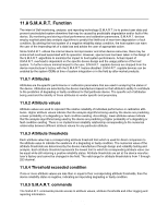
11.5.2 LBA addressing mode Logical sectors on the device shall be linearly mapped with the first LBA addressed sector (sector 0) being the same sector as the first logical CHS addressed sector ( cylinder 0, head 0, sector 1). Irrespective of the logical CHS translation mode currently in effect, the LBA address of a given logical sector does not change. The following formula is always true: LBA = ((cylinder x heads_per_cylinder + heads) x sectors_per_track) + sector - 1 where heads_per_cylinder and sectors_per_track are the current translation mode values. On LBA addressing mode, the LBA value is set to the following register: Device/Head Cylinder High Cylinder Low Sector Number
-
 1
1 -
2
-
3
-
4
-
5
-
6
-
7
-
8
-
9
-
10
-
11
-
12
-
13
-
14
-
15
-
16
-
17
-
18
-
19
-
20
-
21
-
22
-
23
-
24
-
25
-
26
-
27
-
28
-
29
-
30
-
31
-
32
-
33
-
34
-
35
-
36
-
37
-
38
-
39
-
40
-
41
-
42
-
43
-
44
-
45
-
46
-
47
-
48
-
49
-
50
-
51
-
52
-
53
-
54
-
55
-
56
-
57
-
58
-
59
-
60
-
61
-
62
-
63
-
64
-
65
-
66
-
67
-
68
-
69
-
70
-
71
-
72
-
73
-
74
-
75
-
76
-
77
-
78
-
79
-
80
-
81
-
82
-
83
-
84
-
85
-
86
-
 87
87 -
 88
88 -
 89
89 -
 90
90 -
 91
91 -
 92
92 -
 93
93 -
 94
94 -
 95
95 -
 96
96 -
 97
97 -
98
-
99
-
100
-
101
-
102
-
103
-
104
-
105
-
106
-
107
-
108
-
109
-
110
-
111
-
112
-
113
-
114
-
115
-
116
-
117
-
118
-
119
-
120
-
121
-
122
-
123
-
124
-
125
-
126
-
127
-
128
-
129
-
130
-
131
-
132
-
133
-
134
-
135
-
136
-
137
-
138
-
139
-
140
-
141
-
142
-
143
-
144
-
145
-
146
-
147
-
148
-
149
-
150
-
151
-
152
-
153
-
154
-
155
-
156
-
157
-
158
-
159
-
160
-
161
-
162
-
163
-
164
-
165
-
166
-
167
-
168
-
169
-
170
-
171
-
172
-
173
-
174
-
175
-
176
-
177
-
178
-
179
-
180
-
181
-
182
-
183
-
184
-
185
-
186
-
187
-
188
-
189
-
190
-
191
-
192
-
193
-
194
-
195
-
196
-
197
-
198
-
199
-
200
-
201
-
202
-
203
-
204
-
205
-
206
-
207
-
208
-
209
-
210
-
211
-
212
-
213
-
214
-
215
-
216
-
217
 |
 |

11.5.2 LBA addressing mode
Logical sectors on the device shall be linearly mapped with the first LBA addressed sector (sector 0) being
the same sector as the first logical CHS addressed sector ( cylinder 0, head 0, sector 1). Irrespective of
the logical CHS translation mode currently in effect, the LBA address of a given logical sector does not
change. The following formula
is always true:
LBA = ((cylinder x heads_per_cylinder + heads) x sectors_per_track) +
sector - 1
where heads_per_cylinder and sectors_per_track are the current translation mode values.
On LBA addressing mode, the LBA value is set to the following register:
<- - -
LBA bits
7–0
Sector Number
<- - -
LBA bits 15–8
Cylinder Low
<- - -
LBA bits 23–16
Cylinder High
<- - -
LBA bits 27–24
Device/Head
Hitachi Travelstar 60GH & 40GN hard disk drive specifications
79