Hitachi IC25N040ATCS04-0 Specifications - Page 54
Electrical interface specifications
 |
UPC - 683728198664
View all Hitachi IC25N040ATCS04-0 manuals
Add to My Manuals
Save this manual to your list of manuals |
Page 54 highlights
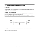
7.0 Electrical interface specifications 7.1 Cabling The maximum cable length from the host system to the hard disk drive plus circuit pattern length in the host system shall not exceed 18 inches. 7.2 Interface connector The signal connector for AT attachment is designed to mate with the 50 pin plug specified in Annex A, Connectors and Cable Assembly, of the ATA/ATAPI-5 document. The figure below and Figure 6.5.2 on page 31 show the connector location and physical pin location. Pin 43 19 1 CA 44 22 2 DB Pin Pin position 20 is left blank for correct connector insertion. Pin positions A, B, C, and D are used for the drive address setting. (Refer to Figure 48 on page 58 for correct address setting.) Figure 34. Interface connector pin assignments Hitachi Travelstar 60GH & 40GN hard disk drive specifications 41
-
 1
1 -
2
-
3
-
4
-
5
-
6
-
7
-
8
-
9
-
10
-
11
-
12
-
13
-
14
-
15
-
16
-
17
-
18
-
19
-
20
-
21
-
22
-
23
-
24
-
25
-
26
-
27
-
28
-
29
-
30
-
31
-
32
-
33
-
34
-
35
-
36
-
37
-
38
-
39
-
40
-
41
-
42
-
43
-
44
-
45
-
46
-
47
-
48
-
 49
49 -
 50
50 -
 51
51 -
 52
52 -
 53
53 -
 54
54 -
 55
55 -
 56
56 -
 57
57 -
 58
58 -
 59
59 -
60
-
61
-
62
-
63
-
64
-
65
-
66
-
67
-
68
-
69
-
70
-
71
-
72
-
73
-
74
-
75
-
76
-
77
-
78
-
79
-
80
-
81
-
82
-
83
-
84
-
85
-
86
-
87
-
88
-
89
-
90
-
91
-
92
-
93
-
94
-
95
-
96
-
97
-
98
-
99
-
100
-
101
-
102
-
103
-
104
-
105
-
106
-
107
-
108
-
109
-
110
-
111
-
112
-
113
-
114
-
115
-
116
-
117
-
118
-
119
-
120
-
121
-
122
-
123
-
124
-
125
-
126
-
127
-
128
-
129
-
130
-
131
-
132
-
133
-
134
-
135
-
136
-
137
-
138
-
139
-
140
-
141
-
142
-
143
-
144
-
145
-
146
-
147
-
148
-
149
-
150
-
151
-
152
-
153
-
154
-
155
-
156
-
157
-
158
-
159
-
160
-
161
-
162
-
163
-
164
-
165
-
166
-
167
-
168
-
169
-
170
-
171
-
172
-
173
-
174
-
175
-
176
-
177
-
178
-
179
-
180
-
181
-
182
-
183
-
184
-
185
-
186
-
187
-
188
-
189
-
190
-
191
-
192
-
193
-
194
-
195
-
196
-
197
-
198
-
199
-
200
-
201
-
202
-
203
-
204
-
205
-
206
-
207
-
208
-
209
-
210
-
211
-
212
-
213
-
214
-
215
-
216
-
217
 |
 |
