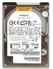
Hitachi IC25N040ATCS04-0 Specifications - Page 83
Drive Address Register, 8 Device/Head Register
 |
UPC - 683728198664
View all Hitachi IC25N040ATCS04-0 manuals
Add to My Manuals
Save this manual to your list of manuals |
Page 83 highlights
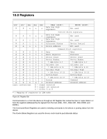
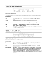
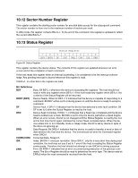
10.7 Drive Address Register Drive Address Register 7 6 5 4 3 2 1 0 HIZ -WTG -H3 -H2 -H1 -H0 -DS1 -DS0 Figure 53. Drive Address Register This register contains the inverted drive select and head select addresses of the currently selected drive. Bit Definitions HIZ -WTG -H3, -H2, -H1, -H0 -DS1 -DS0 High Impedance. This bit is not a device and will always be in a high impedance state. -Write Gate. This bit is 0 when writing to the disk device is in progress. -Head Select. These four bits are the one's complement of the binary coded address of the currently selected head. Bit -H0 is the least significant. -Drive Select 1. The Drive Select bit for device 1 is active low. DS1 = 0 when device 1 (slave) is selected and active. -Drive Select 0. The Drive Select bit for device 0 is active low. DS0 = 0 when device 0 (master) is selected and active. 10.8 Device/Head Register Device/Head Register 7 6 5 4 3 2 1 0 1 L 1 DRV HS3 HS2 HS1 HS0 Figure 54. Device/Head Register This register contains the device and head numbers. Bit Definitions L DRV HS3, HS2, HS0 Binary encoded address mode select. When L = 0, addressing is by CHS mode. When L = 1, addressing is by LBA mode. Device. When DRV = 0, device 0 (master) is selected. When DRV = 1, device 1 (Slave) is selected. Head Select. These four bits indicate the binary encoded address of the head. Bit HS0 is the least significant bit. At command completion, these bits are updated to reflect the currently selected head. The head number may be from zero to the number of heads minus one. In LBA mode, HS3 through HS0 contain bits 24-27 of the LBA. At command completion, these bits are updated to reflect the current LBA bits 24-27. Hitachi Travelstar 60GH & 40GN hard disk drive specifications 70
-
 1
1 -
2
-
3
-
4
-
5
-
6
-
7
-
8
-
9
-
10
-
11
-
12
-
13
-
14
-
15
-
16
-
17
-
18
-
19
-
20
-
21
-
22
-
23
-
24
-
25
-
26
-
27
-
28
-
29
-
30
-
31
-
32
-
33
-
34
-
35
-
36
-
37
-
38
-
39
-
40
-
41
-
42
-
43
-
44
-
45
-
46
-
47
-
48
-
49
-
50
-
51
-
52
-
53
-
54
-
55
-
56
-
57
-
58
-
59
-
60
-
61
-
62
-
63
-
64
-
65
-
66
-
67
-
68
-
69
-
70
-
71
-
72
-
73
-
74
-
75
-
76
-
77
-
 78
78 -
 79
79 -
 80
80 -
 81
81 -
 82
82 -
 83
83 -
 84
84 -
 85
85 -
 86
86 -
 87
87 -
 88
88 -
89
-
90
-
91
-
92
-
93
-
94
-
95
-
96
-
97
-
98
-
99
-
100
-
101
-
102
-
103
-
104
-
105
-
106
-
107
-
108
-
109
-
110
-
111
-
112
-
113
-
114
-
115
-
116
-
117
-
118
-
119
-
120
-
121
-
122
-
123
-
124
-
125
-
126
-
127
-
128
-
129
-
130
-
131
-
132
-
133
-
134
-
135
-
136
-
137
-
138
-
139
-
140
-
141
-
142
-
143
-
144
-
145
-
146
-
147
-
148
-
149
-
150
-
151
-
152
-
153
-
154
-
155
-
156
-
157
-
158
-
159
-
160
-
161
-
162
-
163
-
164
-
165
-
166
-
167
-
168
-
169
-
170
-
171
-
172
-
173
-
174
-
175
-
176
-
177
-
178
-
179
-
180
-
181
-
182
-
183
-
184
-
185
-
186
-
187
-
188
-
189
-
190
-
191
-
192
-
193
-
194
-
195
-
196
-
197
-
198
-
199
-
200
-
201
-
202
-
203
-
204
-
205
-
206
-
207
-
208
-
209
-
210
-
211
-
212
-
213
-
214
-
215
-
216
-
217
 |
 |
