IBM 88772ru User Guide - Page 21
Locator, Information, System-error, Release, latch, connectors, drive, activity, status, DVD-eject,
 |
UPC - 000435948922
View all IBM 88772ru manuals
Add to My Manuals
Save this manual to your list of manuals |
Page 21 highlights
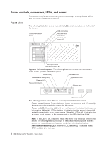
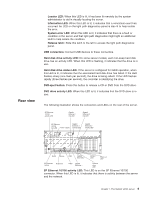
Rear view Locator LED: When this LED is lit, it has been lit remotely by the system administrator to aid in visually locating the server. Information LED: When this LED is lit, it indicates that a noncritical event has occurred. An LED on the light path diagnostics panel is also lit to help isolate the error. System-error LED: When this LED is lit, it indicates that there is a fault or condition in the server and that light path diagnostics might light an additional LED to help isolate the condition. Release latch: Slide this latch to the left to access the light path diagnostics panel. USB connectors: Connect USB devices to these connectors. Hard disk drive activity LED: On some server models, each hot-swap hard disk drive has an activity LED. When this LED is flashing, it indicates that the drive is in use. Hard disk drive status LED: If the server is configured for RAID operation, when this LED is lit, it indicates that the associated hard disk drive has failed. If the LED flashes slowly (one flash per second), the drive is being rebuilt. If the LED flashes rapidly (three flashes per second), the controller is identifying the drive. DVD-eject button: Press this button to release a CD or DVD from the DVD drive. DVD drive activity LED: When this LED is lit, it indicates that the DVD drive is in use. The following illustration shows the connectors and LEDs on the rear of the server. SP Ethernet 10/100 activity LED Gigabit Ethernet 1 link LED Gigabit Ethernet 2 link LED SP Ethernet 10/100 link LED Power supply Gigabit Ethernet 1 activity LED Gigabit Ethernet 2 activity LED Serial Mouse USB Gigabit Ethernet 2 Locator LED Power-on LED SP Ethernet 10/100 Keyboard Video Gigabit Ethernet 1 Systemerror LED SP Ethernet 10/100 activity LED: This LED is on the SP Ethernet 10/100 connector. When this LED is lit, it indicates that there is activity between the server and the network. Chapter 1. The System x3755 server 9
-
 1
1 -
2
-
3
-
4
-
5
-
6
-
7
-
8
-
9
-
10
-
11
-
12
-
13
-
14
-
15
-
 16
16 -
 17
17 -
 18
18 -
 19
19 -
 20
20 -
 21
21 -
 22
22 -
 23
23 -
 24
24 -
 25
25 -
 26
26 -
27
-
28
-
29
-
30
-
31
-
32
-
33
-
34
-
35
-
36
-
37
-
38
-
39
-
40
-
41
-
42
-
43
-
44
-
45
-
46
-
47
-
48
-
49
-
50
-
51
-
52
-
53
-
54
-
55
-
56
-
57
-
58
-
59
-
60
-
61
-
62
-
63
-
64
-
65
-
66
-
67
-
68
-
69
-
70
-
71
-
72
-
73
-
74
-
75
-
76
-
77
-
78
-
79
-
80
-
81
-
82
-
83
-
84
-
85
-
86
-
87
-
88
-
89
-
90
-
91
-
92
-
93
-
94
-
95
-
96
 |
 |
