IBM 88772ru User Guide - Page 49
additional
 |
UPC - 000435948922
View all IBM 88772ru manuals
Add to My Manuals
Save this manual to your list of manuals |
Page 49 highlights
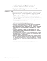
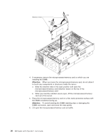
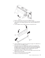
Air baffle 7. Open the retaining clip on each end of the DIMM connector. 8. Touch the static-protective package that contains the DIMM to any unpainted metal surface on the outside of the server; then, remove the DIMM from the package. 9. Turn the DIMM so that the DIMM keys align correctly with the slot. DIMM Retaining clip 10. Insert the DIMM into the connector by aligning the edges of the DIMM with the slots at the ends of the DIMM connector. 11. Firmly press one end of the DIMM into the connector; then, press the other end into the connector. The retaining clips snap into the locked position when the DIMM is seated in the connector. If there is a gap between the DIMM and the retaining clips, the DIMM has not been correctly inserted; open the retaining clips, remove the DIMM, and then reinsert it. 12. Repeat steps 7 through 11 to install the second DIMM in the pair and for each additional pair that you install. 13. Close the microprocessor/memory card air baffle. 14. Replace the microprocessor/memory card: Chapter 2. Installing optional devices 37
-
 1
1 -
2
-
3
-
4
-
5
-
6
-
7
-
8
-
9
-
10
-
11
-
12
-
13
-
14
-
15
-
16
-
17
-
18
-
19
-
20
-
21
-
22
-
23
-
24
-
25
-
26
-
27
-
28
-
29
-
30
-
31
-
32
-
33
-
34
-
35
-
36
-
37
-
38
-
39
-
40
-
41
-
42
-
43
-
 44
44 -
 45
45 -
 46
46 -
 47
47 -
 48
48 -
 49
49 -
 50
50 -
 51
51 -
 52
52 -
 53
53 -
 54
54 -
55
-
56
-
57
-
58
-
59
-
60
-
61
-
62
-
63
-
64
-
65
-
66
-
67
-
68
-
69
-
70
-
71
-
72
-
73
-
74
-
75
-
76
-
77
-
78
-
79
-
80
-
81
-
82
-
83
-
84
-
85
-
86
-
87
-
88
-
89
-
90
-
91
-
92
-
93
-
94
-
95
-
96
 |
 |
