IBM 88772ru User Guide - Page 22
Ethernet, Power-supply, connector, Gigabit, activity, Power-on, Locator, System-error, Video, Mouse
 |
UPC - 000435948922
View all IBM 88772ru manuals
Add to My Manuals
Save this manual to your list of manuals |
Page 22 highlights
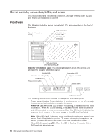
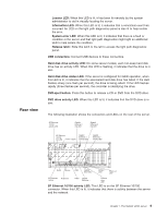
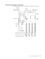
SP Ethernet 10/100 link LED: This LED is on the SP Ethernet 10/100 connector. When this LED is lit, it indicates that there is an active connection on the Ethernet port. Power-supply connector: Connect the power cord to this connector. Gigabit Ethernet 1 link LED: This LED is on the Gigabit Ethernet 1 connector. When this LED is lit, it indicates that there is an active connection on the Ethernet port. Gigabit Ethernet 1 activity LED: This LED is on the Gigabit Ethernet 1 connector. When this LED flashes, it indicates that there is activity between the server and the network. Gigabit Ethernet 2 link LED: This LED is on the Gigabit Ethernet 2 connector. When this LED is lit, it indicates that there is an active connection on the Ethernet port. Gigabit Ethernet 2 activity LED: This LED is on the Gigabit Ethernet 2 connector. When this LED flashes, it indicates that there is activity between the server and the network. Power-on LED: When this LED is lit and not flashing, it indicates that the server is turned on. When this LED is flashing, it indicates that the server is turned off and still connected to an ac power source. When this LED is off, it indicates that ac power is not present, or the power supply or the LED itself has failed. Note: If this LED is off, it does not mean that there is no electrical power in the server. The LED might be burned out. To remove all electrical power from the server, you must disconnect the power cords from the electrical outlets. Locator LED: When this LED is lit, it has been lit remotely by the system administrator to aid in visually locating the server. System-error LED: When this LED is lit, it indicates that there is a fault or condition in the server and that light path diagnostics might light an additional LED to help isolate the condition. Gigabit Ethernet 2 connector: Use this connector to connect the server to a network. Gigabit Ethernet 1 connector: Use this connector to connect the server to a network. USB connector: Connect a USB device to this connector. Video connector: Connect a monitor to this connector. Mouse connector: Connect a mouse or other device to this connector. Keyboard connector: Connect a keyboard to this connector. Serial connector: Connect a 9-pin serial device to this connector. The serial port is shared with the baseboard management controller (BMC). The BMC can take control of the shared serial port to perform text console redirection and to redirect serial traffic, using Serial over LAN (SOL). 10 IBM System x3755 Type 8877: User's Guide
-
 1
1 -
2
-
3
-
4
-
5
-
6
-
7
-
8
-
9
-
10
-
11
-
12
-
13
-
14
-
15
-
16
-
 17
17 -
 18
18 -
 19
19 -
 20
20 -
 21
21 -
 22
22 -
 23
23 -
 24
24 -
 25
25 -
 26
26 -
 27
27 -
28
-
29
-
30
-
31
-
32
-
33
-
34
-
35
-
36
-
37
-
38
-
39
-
40
-
41
-
42
-
43
-
44
-
45
-
46
-
47
-
48
-
49
-
50
-
51
-
52
-
53
-
54
-
55
-
56
-
57
-
58
-
59
-
60
-
61
-
62
-
63
-
64
-
65
-
66
-
67
-
68
-
69
-
70
-
71
-
72
-
73
-
74
-
75
-
76
-
77
-
78
-
79
-
80
-
81
-
82
-
83
-
84
-
85
-
86
-
87
-
88
-
89
-
90
-
91
-
92
-
93
-
94
-
95
-
96
 |
 |
