IBM DTTA-351010 Hard Drive Specifications - Page 46
Jumper Settings
 |
View all IBM DTTA-351010 manuals
Add to My Manuals
Save this manual to your list of manuals |
Page 46 highlights
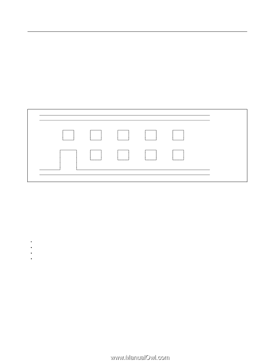
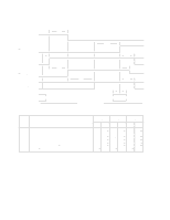
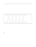
6.3 Jumper Settings 6.3.1 Location of Jumper Pin Jumper pins are located between power pins and AT interface pins. Refer to 6.7.3, " Connector Locations" on page 51 for location of the jumper pins. Pin position A is indicated in the figure. 6.3.2 Jumper Pin Assignment Pin number A through I are prepared for jumper setting. / / / / / / / / / I G E C A / / / / / / / / H F D B / / / / / / / / / Figure 30. Jumper Pin Assignment 6.3.3 Jumper Function Device 0, Device 1, Cable Select, and Device 0 Forcing Device 1 Present can be selected exclussively with one of the following conditions. Default Logical Head 16 Default Logical Head 15 Capacity Clip to 2GB (Default Logical Head 16) Disable Auto Spin (Default Logical Head 16) 38 OEM Specifications for DTTA-3xxxxx
-
 1
1 -
2
-
3
-
4
-
5
-
6
-
7
-
8
-
9
-
10
-
11
-
12
-
13
-
14
-
15
-
16
-
17
-
18
-
19
-
20
-
21
-
22
-
23
-
24
-
25
-
26
-
27
-
28
-
29
-
30
-
31
-
32
-
33
-
34
-
35
-
36
-
37
-
38
-
39
-
40
-
 41
41 -
 42
42 -
 43
43 -
 44
44 -
 45
45 -
 46
46 -
 47
47 -
 48
48 -
 49
49 -
 50
50 -
 51
51 -
52
-
53
-
54
-
55
-
56
-
57
-
58
-
59
-
60
-
61
-
62
-
63
-
64
-
65
-
66
-
67
-
68
-
69
-
70
-
71
-
72
-
73
-
74
-
75
-
76
-
77
-
78
-
79
-
80
-
81
-
82
-
83
-
84
-
85
-
86
-
87
-
88
-
89
-
90
-
91
-
92
-
93
-
94
-
95
-
96
-
97
-
98
-
99
-
100
-
101
-
102
-
103
-
104
-
105
-
106
-
107
-
108
-
109
-
110
-
111
-
112
-
113
-
114
-
115
-
116
-
117
-
118
-
119
-
120
-
121
-
122
-
123
-
124
-
125
-
126
-
127
-
128
-
129
-
130
-
131
-
132
-
133
-
134
-
135
-
136
-
137
-
138
-
139
-
140
-
141
-
142
-
143
-
144
-
145
-
146
-
147
-
148
-
149
-
150
-
151
-
152
-
153
-
154
-
155
-
156
-
157
-
158
-
159
-
160
-
161
-
162
-
163
-
164
-
165
-
166
-
167
-
168
-
169
-
170
-
171
-
172
-
173
-
174
-
175
-
176
-
177
-
178
-
179
-
180
-
181
-
182
-
183
-
184
-
185
-
186
-
187
-
188
 |
 |