Icom IC-M802 Instruction Manual - Page 15
If Filter Width Indicator
 |
View all Icom IC-M802 manuals
Add to My Manuals
Save this manual to your list of manuals |
Page 15 highlights
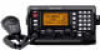
2 PANEL DESCRIPTION q RECEIVE INDICATOR "RX" appears when signals are received or the squelch is open. w TUNE INDICATOR "TUNE" blinks while tuning, if an optional external antenna tuner is connected. (p. 10) • "TUNE" appears after tuning is completed with AT-140, AT-130/E and AH-3. • "THRU" appears when the tuner through function is activated. (This function is available only when connecting AT-140 or AH-3.) • "SWR" appears when the antenna SWR worsens during transmit, depending on the transmit output power. If it appears, check your antenna system. e OPERATING MODE INDICATOR Shows the selected operating mode. •"J3E," "USB," "H3E," "AM," "LSB," "J2B," "AFS," "F1B" "FSK," "A1A" or "CW" appears depending on operating mode and setting. r SIMPLEX/DUPLEX INDICATOR "SIMP" appears when a simplex channel is selected. "DUP" appears when a duplex channel is selected. t FUNCTION INDICATOR " " appears when a secondary function can be accessed. y IF FILTER WIDTH INDICATOR Shows the selected IF filter passband width during e-mail operation mode. u CLARITY INDICATOR (p. 12) "CLAR" appears when the clarity function is activated and shows shifting frequency in "Hz." i SPEAKER OFF INDICATOR " SP " appears when the speaker output is turned OFF. o AGC OFF INDICATOR (p. 11) " AGC" appears when the AGC OFF function is turned ON. !0 POSITION/UTC TIME INDICATOR (p. 16) Shows position and/or UTC (or local) time. When an NMEA0183 ver. 3.01 data is applied to [GPS], the indication is up dated automatically. • When no NMEA data is applied, the position and UTC time must be set in advance. • "GPS" appears when an NMEA0183 ver. 3.01 data is applied to [GPS], "MNL" appears when the position is manually set. • "UTC" appears when the offset time has not been programmed. (No "UTC" indication when offset time is programmed and shows local time.) !1 CHANNEL NUMBER INDICATION Shows the selected channel number. !2 S/RF INDICATOR Shows relative transmit output power levels during transmit and receiving signal strength during receive. !3 NOISE BLANKER INDICATOR (p. 11) "NB" appears when the noise blanker function is activated. !4 SQUELCH INDICATOR (p. 11) "SQL" appears when the squelch is ON. !5 TRANSMIT INDICATOR ➥ "TX" appears during transmit. ➥ "TX" blinks while monitoring a transmit frequency. (p. 10) !6 CHANNEL NAME/RECEIVE FREQUENCY 2 READOUT ➥ Shows the programmed channel names. ➥ Shows receive frequency when no channel name is programmed, or during frequency indication. ➥ During DSC watch mode, displays "DSC WATCH." !7 TRANSMIT FREQUENCY READOUT Shows transmit frequency. !8 OPERATING GUIDE INDICATION During DSC watch mode operation, shows several types of guidance, according to the selected condition. !9 SCANNING FREQUENCY READOUT During DSC watch mode operation, shows the programmed scan frequency. • Decimal points blink. 7
-
 1
1 -
2
-
3
-
4
-
5
-
6
-
7
-
8
-
9
-
 10
10 -
 11
11 -
 12
12 -
 13
13 -
 14
14 -
 15
15 -
 16
16 -
 17
17 -
 18
18 -
 19
19 -
 20
20 -
21
-
22
-
23
-
24
-
25
-
26
-
27
-
28
-
29
-
30
-
31
-
32
-
33
-
34
-
35
-
36
-
37
-
38
-
39
-
40
-
41
-
42
-
43
-
44
-
45
-
46
-
47
-
48
-
49
-
50
-
51
-
52
-
53
-
54
-
55
-
56
-
57
-
58
-
59
-
60
-
61
-
62
-
63
-
64
-
65
-
66
-
67
-
68
-
69
-
70
-
71
-
72
-
73
-
74
-
75
-
76
-
77
-
78
 |
 |
