Icom IC-M802 Instruction Manual - Page 66
Using the optional MB-75
 |
View all Icom IC-M802 manuals
Add to My Manuals
Save this manual to your list of manuals |
Page 66 highlights
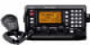
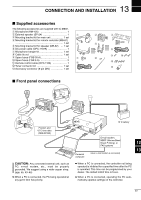
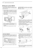
13 CONFECTION AND INSTALLATION I Using the optional MB-75 The optional MB-75 flush mount is available for mounting the controller and speaker to a flat surface such as an instrument panel. q Using the template on the page 67 for the remote controller (RC-25), and page 69 for the speaker (SP-24), carefully cut a hole into the instrument panel (or wherever you plan to mount the controller or the speaker). w Slide the controller or the speaker through the hole as shown below. CAUTION: KEEP the transceiver and microphone at least 1 meter away from your ship's magnetic navigation compass. e Attach the supplied 2 screws (M5×8) and spacers on either side of the controller or speaker. r Attach the clamps on either side of the controller or speaker. • Make sure that the clamps align parallel to the body. t Tighten the end screws on the clamps (rotate clockwise) so that the clamps press firmly against the inside of the instrument control panel. y Tighten the locking nuts (rotate counterclockwise) so that the controller or speaker is securely mounted in position as below. u Connect the control cable then return the instrument control panel to its original place. ✔ For your reference When flush mounting the controller and speaker side by side as below, screw and spacer attachment for the facing side will be impossible with the instructions above. q Carefully cut the holes with at least 25 mm (1 in) space between them into the instrument panel. w Install the speaker as instructed above, first. e Attach the screw and spacer on the speaker side of the controller. r Slide the controller through the hole as shown below. In this case, refer to the instructions at right for reference. 58 t Attach the screw and spacer on the other side of the controller, then attach the clamps and follow steps t to u as above.
-
 1
1 -
2
-
3
-
4
-
5
-
6
-
7
-
8
-
9
-
10
-
11
-
12
-
13
-
14
-
15
-
16
-
17
-
18
-
19
-
20
-
21
-
22
-
23
-
24
-
25
-
26
-
27
-
28
-
29
-
30
-
31
-
32
-
33
-
34
-
35
-
36
-
37
-
38
-
39
-
40
-
41
-
42
-
43
-
44
-
45
-
46
-
47
-
48
-
49
-
50
-
51
-
52
-
53
-
54
-
55
-
56
-
57
-
58
-
59
-
60
-
 61
61 -
 62
62 -
 63
63 -
 64
64 -
 65
65 -
 66
66 -
 67
67 -
 68
68 -
 69
69 -
 70
70 -
 71
71 -
72
-
73
-
74
-
75
-
76
-
77
-
78
 |
 |
