Intel D101GGC Product Specification - Page 18
PCI Express* Connectors - ram support
 |
View all Intel D101GGC manuals
Add to My Manuals
Save this manual to your list of manuals |
Page 18 highlights
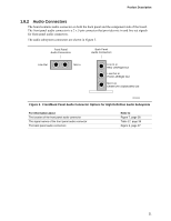
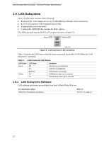
Intel Desktop Board D101GGC Technical Product Specification NOTE Many Serial ATA drives use new low-voltage power connectors and require adaptors or power supplies equipped with low-voltage power connectors. For more information, see: http://www.serialata.org/ For information about The location of the Serial ATA IDE connectors Refer to Figure 7, page 38 1.5.5 Real-Time Clock, CMOS SRAM, and Battery A coin-cell battery (CR2032) powers the real-time clock and CMOS memory. When the computer is not plugged into a wall socket, the battery has an estimated life of three years. When the computer is plugged in, the standby current from the power supply extends the life of the battery. The clock is accurate to ± 13 minutes/year at 25 ºC with 3.3 VSB applied. NOTE If the battery and AC power fail, custom defaults, if previously saved, will be loaded into CMOS RAM at power-on. 1.6 PCI Express* Connectors The board provides the following PCI Express connectors: • One PCI Express x16 connector supporting simultaneous transfer speeds up to 8 GBytes/sec • One PCI Express x1 connector. The x1 interface supports simultaneous transfer speeds up to 500 MBytes/sec The PCI Express interface supports the PCI Conventional bus configuration mechanism so that the underlying PCI Express architecture is compatible with PCI Conventional compliant operating systems. Additional features of the PCI Express interface include the following: • Support for the PCI Express enhanced configuration mechanism • Automatic discovery, link training, and initialization • Support for Active State Power Management (ASPM) • SMBus 2.0 support • Wake# signal supporting wake events from ACPI S1, S3, S4, or S5 • Software compatible with the PCI Power Management Event (PME) mechanism defined in the PCI Power Management Specification Rev. 1.1 18
-
 1
1 -
2
-
3
-
4
-
5
-
6
-
7
-
8
-
9
-
10
-
11
-
12
-
 13
13 -
 14
14 -
 15
15 -
 16
16 -
 17
17 -
 18
18 -
 19
19 -
 20
20 -
 21
21 -
 22
22 -
 23
23 -
24
-
25
-
26
-
27
-
28
-
29
-
30
-
31
-
32
-
33
-
34
-
35
-
36
-
37
-
38
-
39
-
40
-
41
-
42
-
43
-
44
-
45
-
46
-
47
-
48
-
49
-
50
-
51
-
52
-
53
-
54
-
55
-
56
-
57
-
58
-
59
-
60
-
61
-
62
-
63
-
64
-
65
-
66
-
67
-
68
-
69
-
70
-
71
-
72
-
73
-
74
 |
 |
