Intel D101GGC Product Specification - Page 71
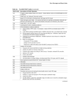
Table 42., Port 80h POST Codes - video controller
 |
View all Intel D101GGC manuals
Add to My Manuals
Save this manual to your list of manuals |
Page 71 highlights
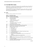
Error Messages and Beep Codes Table 42. Port 80h POST Codes (continued) POST Code 14h 16h 18h 1Bh 1Dh 1Fh 21h 23h 27h 29h 2Dh 33h 3Ch 3Eh 40h 43h 47h 49h 4Eh Description of POST Operation Program chipset default values into chipset. Chipset default values are MODBINable by OEM customers. Initial Early_Init_Onboard_Generator switch. Detect CPU information including brand, SMI type and CPU level. Initial interrupts vector table. If no special interrupts are specified, all hardware interrupts are directed to SPURIOUS_INT_HDLR and software interrupts to SPURIOUS_soft_HDLR. Initial EARLY_PM_INIT switch. Load keyboard matrix (notebook platform) HPM initialization (notebook platform) 1. Check validity of RTC value: for example, a value of 5Ah is an invalid value for RTC minute. 2. Load CMOS settings into BIOS stack. If CMOS checksum fails, use default value instead. 3. Prepare BIOS resource map for PCI and Plug and Play use. If ESCD is valid, take into consideration the ESCD's legacy information. 4. Onboard clock generator initialization. Disable respective clock resource to empty PCI and DIMM slots. 5. Early PCI initialization: - Enumerate PCI bus number - Assign memory and I/O resource - Search for a valid VGA device and VGA BIOS, and put it into C000:0. Initialize INT 09 buffer 1. Program CPU internal MTRR for 0-640K memory address. 2. Initialize the APIC for Pentium class CPU. 3. Program early chipset according to CMOS setup. Example: onboard IDE controller. 4. Measure CPU speed. 5. Invoke video BIOS. 1. Initialize multi-language 2. Put information on screen display, including Award title, CPU type, and CPU speed. Reset keyboard except Winbond 977 series Super I/O chips. Test 8254 Test 8259 interrupt mask bits for channel 1 Test 8259 interrupt mask bits for channel 2 Test 8259 functionality Initialize EISA slot Calculate total memory by testing the last double word of each 64K page. 1. Program MTRR of M1 CPU 2. Initialize L2 cache and program CPU with proper cacheable range. 3. Initialize the APIC. 4. On MP platform, adjust the cacheable range to smaller one in case the cacheable ranges between each CPU are not identical. continued 71
-
 1
1 -
2
-
3
-
4
-
5
-
6
-
7
-
8
-
9
-
10
-
11
-
12
-
13
-
14
-
15
-
16
-
17
-
18
-
19
-
20
-
21
-
22
-
23
-
24
-
25
-
26
-
27
-
28
-
29
-
30
-
31
-
32
-
33
-
34
-
35
-
36
-
37
-
38
-
39
-
40
-
41
-
42
-
43
-
44
-
45
-
46
-
47
-
48
-
49
-
50
-
51
-
52
-
53
-
54
-
55
-
56
-
57
-
58
-
59
-
60
-
61
-
62
-
63
-
64
-
65
-
 66
66 -
 67
67 -
 68
68 -
 69
69 -
 70
70 -
 71
71 -
 72
72 -
 73
73 -
 74
74
 |
 |
