Intel D101GGC Product Specification - Page 35
PCI Configuration Space Map, 6 PCI Conventional Interrupt Routing Map - graphics card
 |
View all Intel D101GGC manuals
Add to My Manuals
Save this manual to your list of manuals |
Page 35 highlights
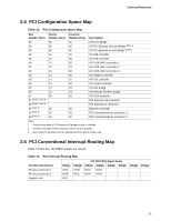
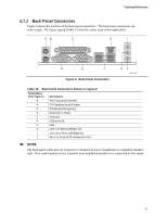
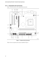
Technical Reference 2.5 PCI Configuration Space Map Table 13. PCI Configuration Space Map Bus Number (hex) 00 00 00 00 00 00 00 00 00 00 00 00 00 01 01 (Notes 1 and 3) 02 (Notes 2 and 3) 02 (Note 3) 03 (Note 3) 03 (Note 3) Device Number (hex) 00 02 06 11 12 13 13 13 14 14 14 14 14 05 02 03 04 Function Number (hex) 00 00 00 00 00 00 01 02 00 01 02 03 04 00 00 00 00 Description ATI Host Bridge ATI PCI Express x16 port Bridge (Note 1) ATI PCI Express x1 port Bridge (Note 2) ATI IDE controller ATI IDE controller ATI USB OHCI controller 1 ATI USB OHCI controller 2 ATI USB OHCI controller 3 ATI SMBus controller ATI IDE controller ATI Azalia controller ATI ISA bridge ATI Decode PCI/PCI bridge ATI VGA controller PCI Express x16 connector PCI Express x1 connector Ethernet controller PCI Conventional bus connector 1 PCI Conventional bus connector 2 Notes: 1. Present only when a PCI Express x16 graphics card is installed. 2. Present only when a PCI Express x1 add-in card is installed. 3. Bus number is dynamic and can change based on add-in cards used. 2.6 PCI Conventional Interrupt Routing Map Table 14 lists how the PIRQ signals are routed. Table 14. PCI Interrupt Routing Map PCI Interrupt Source PCI bus connector 1 PCI bus connector 2 Realtek LAN PIRQA INTA INTB INTF PIRQB INTB INTC IXP 450 PIRQ Signal Name PIRQC PIRQD PIRQE PIRQF INTC INTD INTD INTA PIRQG PIRQH 35
-
 1
1 -
2
-
3
-
4
-
5
-
6
-
7
-
8
-
9
-
10
-
11
-
12
-
13
-
14
-
15
-
16
-
17
-
18
-
19
-
20
-
21
-
22
-
23
-
24
-
25
-
26
-
27
-
28
-
29
-
 30
30 -
 31
31 -
 32
32 -
 33
33 -
 34
34 -
 35
35 -
 36
36 -
 37
37 -
 38
38 -
 39
39 -
 40
40 -
41
-
42
-
43
-
44
-
45
-
46
-
47
-
48
-
49
-
50
-
51
-
52
-
53
-
54
-
55
-
56
-
57
-
58
-
59
-
60
-
61
-
62
-
63
-
64
-
65
-
66
-
67
-
68
-
69
-
70
-
71
-
72
-
73
-
74
 |
 |