Contents
vii
Figures
1.
Block Diagram
..............................................................................................................
11
2.
Board Components
......................................................................................................
12
3.
Front/Back Panel Audio Connector Options for High Definition Audio Subsystem
......
21
4.
LAN Connector LED Locations
....................................................................................
22
5.
Location of the Standby Power Indicator LED
.............................................................
29
6.
Back Panel Connectors
................................................................................................
37
7.
Component-side Connectors
.......................................................................................
38
8.
Connection Diagram for Front Panel Connector
..........................................................
43
9.
Connection Diagram for Front Panel USB Connectors
................................................
44
10.
Location of the Jumper Block
.......................................................................................
45
11.
Board Dimensions
........................................................................................................
46
12.
I/O Shield Dimensions
..................................................................................................
47
13.
Processor Heatsink for Omni-directional Airflow
..........................................................
50
14.
Localized High Temperature Zones
.............................................................................
51
Tables
1.
Feature Summary
........................................................................................................
10
2.
Board Components Shown in Figure 2
........................................................................
13
3.
Supported System Bus Frequency and Memory Speed Combinations
.......................
15
4.
Supported Memory Configurations
..............................................................................
15
5.
LAN Connector LED States
.........................................................................................
22
6.
Effects of Pressing the Power Switch
..........................................................................
24
7.
Power States and Targeted System Power
.................................................................
25
8.
Wake-up Devices and Events
......................................................................................
25
9.
System Memory Map
...................................................................................................
31
10.
DMA Channels
.............................................................................................................
32
11.
I/O Map
........................................................................................................................
33
12.
Interrupts
......................................................................................................................
34
13.
PCI Configuration Space Map
......................................................................................
35
14.
PCI Interrupt Routing Map
...........................................................................................
35
15.
Back Panel Connectors Shown in Figure 6
..................................................................
37
16.
Component-side Connectors Shown in Figure 7
.........................................................
39
17.
Front Panel Audio Connector
.......................................................................................
39
18.
Chassis Intrusion Connector
........................................................................................
40
19.
Serial ATA Connectors
.................................................................................................
40
20.
Processor Fan Connector
............................................................................................
40
21.
Chassis Fan Connectors
..............................................................................................
40
22.
Main Power Connector
.................................................................................................
41
23.
ATX12V Power Connector
...........................................................................................
41
24.
Auxiliary Front Panel Power/Sleep LED Connector
.....................................................
42
25.
Front Panel Connector
.................................................................................................
42
26.
States for a One-Color Power LED
..............................................................................
43
27.
States for a Two-Color Power LED
..............................................................................
43
28.
BIOS Setup Configuration Jumper Settings
.................................................................
45
29.
DC Loading Characteristics
.........................................................................................
48
30.
Fan Connector Current Capability
................................................................................
49
31.
Thermal Considerations for Components
....................................................................
52

 1
1 2
2 3
3 4
4 5
5 6
6 7
7 8
8 9
9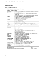 10
10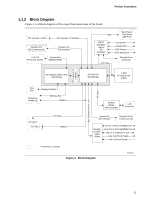 11
11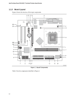 12
12