Intel D101GGC Product Specification - Page 43
Hard Drive Activity LED Connector [Orange], 7.2.4.2, Reset Switch Connector [Blue], 7.2.4.3
 |
View all Intel D101GGC manuals
Add to My Manuals
Save this manual to your list of manuals |
Page 43 highlights
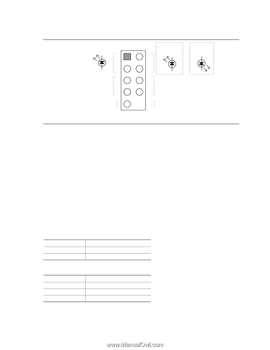
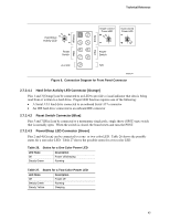
Technical Reference + Hard Drive Activity LED − Reset Switch +5 V DC Blue Orange 12 34 56 78 9 Red Green Single-colored Power LED + − Dual-colored Power LED − + Power Switch N/C OM18249 Figure 8. Connection Diagram for Front Panel Connector 2.7.2.4.1 Hard Drive Activity LED Connector [Orange] Pins 1 and 3 [Orange] can be connected to an LED to provide a visual indicator that data is being read from or written to a hard drive. Proper LED function requires one of the following: • A Serial ATA hard drive connected to an onboard Serial ATA connector • An IDE hard drive connected to an onboard IDE connector 2.7.2.4.2 Reset Switch Connector [Blue] Pins 5 and 7 [Blue] can be connected to a momentary single pole, single throw (SPST) type switch that is normally open. When the switch is closed, the board resets and runs the POST. 2.7.2.4.3 Power/Sleep LED Connector [Green] Pins 2 and 4 [Green] can be connected to a one- or two-color LED. Table 26 shows the possible states for a one-color LED. Table 27 shows the possible states for a two-color LED. Table 26. States for a One-Color Power LED LED State Description Off Steady Green Power off/sleeping Running Table 27. States for a Two-Color Power LED LED State Off Steady Green Steady Yellow Description Power off Running Sleeping 43
-
 1
1 -
2
-
3
-
4
-
5
-
6
-
7
-
8
-
9
-
10
-
11
-
12
-
13
-
14
-
15
-
16
-
17
-
18
-
19
-
20
-
21
-
22
-
23
-
24
-
25
-
26
-
27
-
28
-
29
-
30
-
31
-
32
-
33
-
34
-
35
-
36
-
37
-
 38
38 -
 39
39 -
 40
40 -
 41
41 -
 42
42 -
 43
43 -
 44
44 -
 45
45 -
 46
46 -
 47
47 -
 48
48 -
49
-
50
-
51
-
52
-
53
-
54
-
55
-
56
-
57
-
58
-
59
-
60
-
61
-
62
-
63
-
64
-
65
-
66
-
67
-
68
-
69
-
70
-
71
-
72
-
73
-
74
 |
 |