Intel D101GGC Product Specification - Page 39
Integrator's Note
 |
View all Intel D101GGC manuals
Add to My Manuals
Save this manual to your list of manuals |
Page 39 highlights
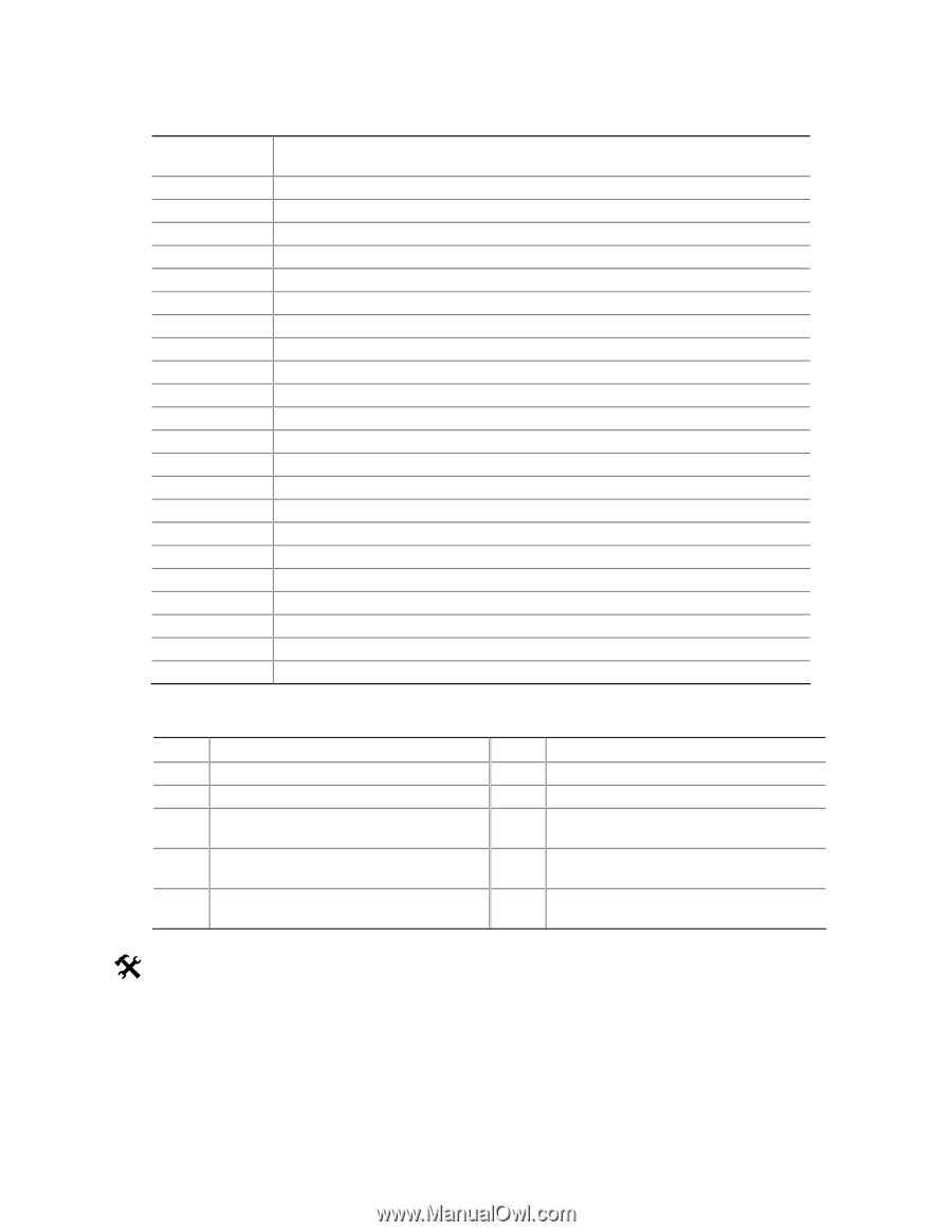
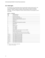
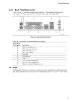
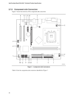
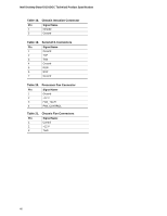
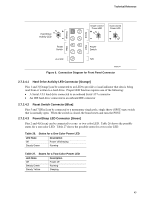
Technical Reference Table 16. Component-side Connectors Shown in Figure 7 Item/callout from Figure 7 Description A PCI Conventional bus add-in card connector 2 B PCI Conventional bus add-in card connector 1 C Front panel audio connector D PCI Express x1 bus add-in card connector E PCI Express x16 add-in card connector F Rear chassis fan connector G +12V power connector (ATX12V) H Processor fan connector I Chassis intrusion connector J Main power connector K Diskette drive connector L Primary parallel ATA IDE connector M Secondary parallel ATA IDE connector N Serial ATA connector 1 O Front chassis fan connector P Serial ATA connector 2 Q Serial ATA connector 4 R Serial ATA connector 3 S Auxiliary front panel power LED connector T Front panel connector U Front panel USB connector V Front panel USB connector Table 17. Front Panel Audio Connector Pin Signal Name Pin 1 Port F Left Channel 2 3 Port F Right Channel 4 5 Port E Right Channel 6 7 Port E and Port F 8 Sense send (jack detection) 9 Port E Left Channel 10 # INTEGRATOR'S NOTE The front panel audio connector is colored yellow. Signal Name Ground Presence# (dongle present) Port F Sense return (jack detection) Key Port E Sense return (jack detection) 39
-
 1
1 -
2
-
3
-
4
-
5
-
6
-
7
-
8
-
9
-
10
-
11
-
12
-
13
-
14
-
15
-
16
-
17
-
18
-
19
-
20
-
21
-
22
-
23
-
24
-
25
-
26
-
27
-
28
-
29
-
30
-
31
-
32
-
33
-
 34
34 -
 35
35 -
 36
36 -
 37
37 -
 38
38 -
 39
39 -
 40
40 -
 41
41 -
 42
42 -
 43
43 -
 44
44 -
45
-
46
-
47
-
48
-
49
-
50
-
51
-
52
-
53
-
54
-
55
-
56
-
57
-
58
-
59
-
60
-
61
-
62
-
63
-
64
-
65
-
66
-
67
-
68
-
69
-
70
-
71
-
72
-
73
-
74
 |
 |