Intel D101GGC Product Specification - Page 70
Port 80h POST Codes - beep codes
 |
View all Intel D101GGC manuals
Add to My Manuals
Save this manual to your list of manuals |
Page 70 highlights
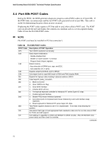
Intel Desktop Board D101GGC Technical Product Specification 4.4 Port 80h POST Codes During the POST, the BIOS generates diagnostic progress codes (POST-codes) to I/O port 80h. If the POST fails, execution stops and the last POST code generated is left at port 80h. This code is useful for determining the point where an error occurred. Displaying the POST-codes requires a PCI bus add-in card, often called a POST card. The POST card can decode the port and display the contents on a medium such as a seven-segment display. Table 42 lists the Port 80h POST codes. NOTE The POST card must be installed in PCI bus connector 1. Table 42. Port 80h POST Codes POST Code CFh C0h C1h C3h C5h 01h 03h 05h 07h 08h 0Ah 0Eh 10h 12h Description of POST Operation Test CMOS read/write functionality Early chipset initialization: - Disable shadow RAM - Disable L2 cache (socket 7 or below) - Program basic chipset registers Detect memory - Auto-detection of DRAM size, type, and ECC. - Auto-detection of L2 cache Expand compressed BIOS code to DRAM Call chipset hook to copy BIOS back to E000 and F000 shadow RAM. Expand the Xgroup codes locating in physical address 1000:0 Initial SuperIO_Early_Init switch. 1. Blank out screen 2. Clear CMOS error flag 1. Clear 8042 interface 2. Initialize 8042 self-test 1. Test special keyboard controller for Winbond 977 series Super I/O chips. 2. Enable keyboard interface. 1. Disable PS/2 mouse interface (optional). 2. Auto-detect ports for keyboard and mouse followed by a port and interface swap (optional). 3. Reset keyboard for Winbond 977 series Super I/O chips. Test F000h segment shadow to see if it is read/writable. If test fails, keep beeping the speaker. Auto-detect flash type to load appropriate flash read/write codes into the run time area in F000 for ESCD and DMI support. Use walking 1's algorithm to check out interface in CMOS circuitry. Also set real-time clock power status and then check for override. continued 70
-
 1
1 -
2
-
3
-
4
-
5
-
6
-
7
-
8
-
9
-
10
-
11
-
12
-
13
-
14
-
15
-
16
-
17
-
18
-
19
-
20
-
21
-
22
-
23
-
24
-
25
-
26
-
27
-
28
-
29
-
30
-
31
-
32
-
33
-
34
-
35
-
36
-
37
-
38
-
39
-
40
-
41
-
42
-
43
-
44
-
45
-
46
-
47
-
48
-
49
-
50
-
51
-
52
-
53
-
54
-
55
-
56
-
57
-
58
-
59
-
60
-
61
-
62
-
63
-
64
-
 65
65 -
 66
66 -
 67
67 -
 68
68 -
 69
69 -
 70
70 -
 71
71 -
 72
72 -
 73
73 -
 74
74
 |
 |