Intel D848PMB Technical Product Specification - Page 30
Integrator, S Note
 |
View all Intel D848PMB manuals
Add to My Manuals
Save this manual to your list of manuals |
Page 30 highlights
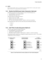
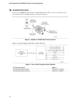
Intel Desktop Board D848PMB Technical Product Specification # INTEGRATOR'S NOTE To access the S/PDIF signal with the 5.1 Digital Shared Jack option, connect an 1/8-inch stereo phone plug to RCA jack adapter/splitter as shown in Figure 4. Connect to S/PDIF output on Back Panel RCA Jack Left Channel (White, if colored) 1/8-inch Stereo Phone Plug Connect to 5.1 speaker system or an S/PDIF decoder OM16108 Figure 4. Adapter for S/PDIF Back Panel Connector Figure 5 is a block diagram of the Flex 6 audio subsystem. 82801EB I/O Controller Hub (ICH5) AC '97 Link AD1985 Audio Codec Rear Left and Right Out Front Left and Right Out Center and LFE (Subwoofer) Out S/PDIF Line In Mic In CD-ROM Auxiliary Line In Figure 5. Flex 6 Audio Subsystem Block Diagram OM16102 For information about The front panel audio connector The back panel audio connectors Refer to Section 2.9.1, page 64 Section 2.8.1, page 51 30
-
 1
1 -
2
-
3
-
4
-
5
-
6
-
7
-
8
-
9
-
10
-
11
-
12
-
13
-
14
-
15
-
16
-
17
-
18
-
19
-
20
-
21
-
22
-
23
-
24
-
 25
25 -
 26
26 -
 27
27 -
 28
28 -
 29
29 -
 30
30 -
 31
31 -
 32
32 -
 33
33 -
 34
34 -
 35
35 -
36
-
37
-
38
-
39
-
40
-
41
-
42
-
43
-
44
-
45
-
46
-
47
-
48
-
49
-
50
-
51
-
52
-
53
-
54
-
55
-
56
-
57
-
58
-
59
-
60
-
61
-
62
-
63
-
64
-
65
-
66
-
67
-
68
-
69
-
70
-
71
-
72
-
73
-
74
-
75
-
76
-
77
-
78
-
79
-
80
-
81
-
82
-
83
-
84
-
85
-
86
-
87
-
88
-
89
-
90
-
91
-
92
-
93
-
94
-
95
-
96
-
97
-
98
-
99
-
100
-
101
-
102
-
103
-
104
-
105
-
106
-
107
-
108
-
109
-
110
-
111
-
112
-
113
-
114
-
115
-
116
-
117
-
118
-
119
-
120
-
121
-
122
 |
 |
