Intel D848PMB Technical Product Specification - Page 32
Gigabit LAN Subsystem Optional - driver ethernet
 |
View all Intel D848PMB manuals
Add to My Manuals
Save this manual to your list of manuals |
Page 32 highlights
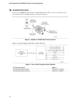
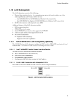
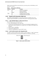
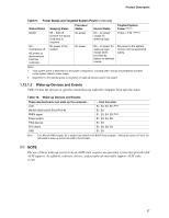
Intel Desktop Board D848PMB Technical Product Specification Table 6 describes the LED states when the board is powered up and the 10/100 Mbits/sec LAN subsystem is operating. Table 6. LAN Connector LED States LED Color Green Yellow LED State Off On Blinking Off On Condition LAN link is not established. LAN link is established. LAN activity is occurring. 10 Mbits/sec data rate is selected. 100 Mbits/sec data rate is selected. 1.10.2 Gigabit LAN Subsystem (Optional) The Gigabit (10/100/1000 Mbits/sec) LAN subsystem includes the GMCH (with its CSA interface), the Intel 82547EI PLC, and an RJ-45 LAN connector with integrated status LEDs. 1.10.2.1 Intel® 82547EI Platform LAN Connect Device Intel 82547EI provides the following functions: • Basic 10/100/1000 Ethernet LAN connectivity • Communication Streaming Architecture (CSA) port provides higher throughput and lower latencies than the Intel 82562EZ device, resulting in up to 30% higher bus throughput (up to wirespeed) • Full device driver compatibility • Programmable transit threshold • Configuration EEPROM that contains the MAC address 1.10.2.2 RJ-45 LAN Connector with Integrated LEDs Two LEDs are built into the RJ-45 LAN connector (as shown in Figure 7). Table 7 describes the LED states when the board is powered up and the Gigabit LAN subsystem is operating. Green LED Green/Yellow LED OM16513 Figure 7. LAN Connector LED Locations 32
-
 1
1 -
2
-
3
-
4
-
5
-
6
-
7
-
8
-
9
-
10
-
11
-
12
-
13
-
14
-
15
-
16
-
17
-
18
-
19
-
20
-
21
-
22
-
23
-
24
-
25
-
26
-
 27
27 -
 28
28 -
 29
29 -
 30
30 -
 31
31 -
 32
32 -
 33
33 -
 34
34 -
 35
35 -
 36
36 -
 37
37 -
38
-
39
-
40
-
41
-
42
-
43
-
44
-
45
-
46
-
47
-
48
-
49
-
50
-
51
-
52
-
53
-
54
-
55
-
56
-
57
-
58
-
59
-
60
-
61
-
62
-
63
-
64
-
65
-
66
-
67
-
68
-
69
-
70
-
71
-
72
-
73
-
74
-
75
-
76
-
77
-
78
-
79
-
80
-
81
-
82
-
83
-
84
-
85
-
86
-
87
-
88
-
89
-
90
-
91
-
92
-
93
-
94
-
95
-
96
-
97
-
98
-
99
-
100
-
101
-
102
-
103
-
104
-
105
-
106
-
107
-
108
-
109
-
110
-
111
-
112
-
113
-
114
-
115
-
116
-
117
-
118
-
119
-
120
-
121
-
122
 |
 |
