Intel D848PMB Technical Product Specification - Page 8

s, Tables - desktop board

Page 8 highlights

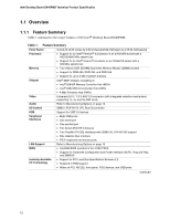
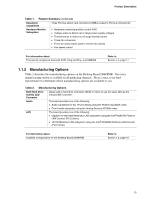
Intel Desktop Board D848PMB Technical Product Specification Figures 1. Desktop Board D848PMB Components 14 2. Block Diagram ...15 3. Back Panel Audio Connector Options for Flex 6 Audio Subsystem 29 4. Adapter for S/PDIF Back Panel Connector 30 5. Flex 6 Audio Subsystem Block Diagram 30 6. LAN Connector LED Locations 31 7. LAN Connector LED Locations 32 8. Thermal Monitoring...34 9. Location of the Standby Power Indicator LED on the D848PMB Board 41 10. Back Panel Connectors 51 11. Audio Connectors ...53 12. Power and Hardware Control Connectors 55 13. D848PMB Add-in Board and Peripheral Interface Connectors 58 14. External I/O Connectors 60 15. Connection Diagram for Front Panel Connector 61 16. Connection Diagram for Front Panel USB Connectors 63 17. Location of the Jumper Blocks 64 18. Desktop Board D848PMB Dimensions 66 19. I/O Shield Dimensions 67 20. Localized High Temperature Zones 70 Tables 1. Feature Summary...12 2. Manufacturing Options 13 3. Specifications ...17 4. Supported System Bus Frequency and Memory Speed Combinations 21 5. Supported Memory Configurations 22 6. LAN Connector LED States 32 7. LAN Connector LED States 33 8. Effects of Pressing the Power Switch 36 9. Power States and Targeted System Power 36 10. Wake-up Devices and Events 37 11. Fan Connector Function/Operation 39 12. System Memory Map 44 13. DMA Channels ...44 14. I/O Map ...45 15. PCI Configuration Space Map 46 16. PCI Configuration Space Bus Number Options 46 17. Interrupts ...47 18. PCI Interrupt Routing Map 49 19. Front Panel Audio Connector 54 20. ATAPI CD-ROM Connector 54 21. S/PDIF Connector ...54 22. Auxiliary Line In Connector 54 23. Rear Chassis Fan Connector 55 viii

  • 1
  • 2
  • 3
  • 4
  • 5
  • 6
  • 7
  • 8
  • 9
  • 10
  • 11
  • 12
  • 13
  • 14
  • 15
  • 16
  • 17
  • 18
  • 19
  • 20
  • 21
  • 22
  • 23
  • 24
  • 25
  • 26
  • 27
  • 28
  • 29
  • 30
  • 31
  • 32
  • 33
  • 34
  • 35
  • 36
  • 37
  • 38
  • 39
  • 40
  • 41
  • 42
  • 43
  • 44
  • 45
  • 46
  • 47
  • 48
  • 49
  • 50
  • 51
  • 52
  • 53
  • 54
  • 55
  • 56
  • 57
  • 58
  • 59
  • 60
  • 61
  • 62
  • 63
  • 64
  • 65
  • 66
  • 67
  • 68
  • 69
  • 70
  • 71
  • 72
  • 73
  • 74
  • 75
  • 76
  • 77
  • 78
  • 79
  • 80
  • 81
  • 82
  • 83
  • 84
  • 85
  • 86
  • 87
  • 88
  • 89
  • 90
  • 91
  • 92
  • 93
  • 94
  • 95
  • 96
  • 97
  • 98
  • 99
  • 100
  • 101
  • 102
  • 103
  • 104
  • 105
  • 106
  • 107
  • 108
  • 109
  • 110
  • 111
  • 112
  • 113
  • 114
  • 115
  • 116
  • 117
  • 118
  • 119
  • 120
  • 121
  • 122

Intel Desktop Board D848PMB Technical Product Specification
viii
Figures
1.
Desktop Board D848PMB Components
......................................................................
14
2.
Block Diagram
............................................................................................................
15
3.
Back Panel Audio Connector Options for Flex 6 Audio Subsystem
............................
29
4.
Adapter for S/PDIF Back Panel Connector
.................................................................
30
5.
Flex 6 Audio Subsystem Block Diagram
.....................................................................
30
6.
LAN Connector LED Locations
...................................................................................
31
7.
LAN Connector LED Locations
...................................................................................
32
8.
Thermal Monitoring
.....................................................................................................
34
9.
Location of the Standby Power Indicator LED on the D848PMB Board
......................
41
10.
Back Panel Connectors
..............................................................................................
51
11.
Audio Connectors
.......................................................................................................
53
12.
Power and Hardware Control Connectors
..................................................................
55
13.
D848PMB Add-in Board and Peripheral Interface Connectors
....................................
58
14.
External I/O Connectors
.............................................................................................
60
15.
Connection Diagram for Front Panel Connector
.........................................................
61
16.
Connection Diagram for Front Panel USB Connectors
...............................................
63
17.
Location of the Jumper Blocks
....................................................................................
64
18.
Desktop Board D848PMB Dimensions
.......................................................................
66
19.
I/O Shield Dimensions
................................................................................................
67
20.
Localized High Temperature Zones
............................................................................
70
Tables
1.
Feature Summary
.......................................................................................................
12
2.
Manufacturing Options
...............................................................................................
13
3.
Specifications
.............................................................................................................
17
4.
Supported System Bus Frequency and Memory Speed Combinations
.......................
21
5.
Supported Memory Configurations
.............................................................................
22
6.
LAN Connector LED States
........................................................................................
32
7.
LAN Connector LED States
........................................................................................
33
8.
Effects of Pressing the Power Switch
.........................................................................
36
9.
Power States and Targeted System Power
................................................................
36
10.
Wake-up Devices and Events
.....................................................................................
37
11.
Fan Connector Function/Operation
.............................................................................
39
12.
System Memory Map
..................................................................................................
44
13.
DMA Channels
...........................................................................................................
44
14.
I/O Map
......................................................................................................................
45
15.
PCI Configuration Space Map
....................................................................................
46
16.
PCI Configuration Space Bus Number Options
..........................................................
46
17.
Interrupts
....................................................................................................................
47
18.
PCI Interrupt Routing Map
..........................................................................................
49
19.
Front Panel Audio Connector
.....................................................................................
54
20.
ATAPI CD-ROM Connector
........................................................................................
54
21.
S/PDIF Connector
......................................................................................................
54
22.
Auxiliary Line In Connector
.........................................................................................
54
23.
Rear Chassis Fan Connector
.....................................................................................
55