Intel S3420GPLC Product Specification - Page 104
CMOS Clear and Password Reset Usage Procedure
 |
UPC - 735858211819
View all Intel S3420GPLC manuals
Add to My Manuals
Save this manual to your list of manuals |
Page 104 highlights
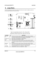
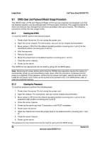
Jumper Blocks Intel® Server Board S3420GP TPS 8.1 CMOS Clear and Password Reset Usage Procedure The CMOS Clear (J1F5) and Password Reset (J1F2) recovery features are designed such that the desired operation can be achieved with minimal system downtime. The usage procedure for these two features has changed from previous generation Intel server boards. The following procedure outlines the new usage model. 8.1.1 Clearing the CMOS To clear the CMOS, perform the following steps: 1. Power down the server. Do not unplug the power cord. 2. Open the server chassis. For instructions, see your server chassis documentation. 3. Move jumper (J1F5) from the default operating position (covering pins 1 and 2) to the reset/clear position (covering pins 2 and 3). 4. Wait five seconds. 5. Remove AC power. 6. Move the jumper back to the default position (covering pins 1 and 2). 7. Close the server chassis. 8. Power up the server. The CMOS is now cleared and can be reset by going into the BIOS setup. Note: Removing AC power before performing the CMOS clear operation causes the system to automatically power up and immediately power down, after the procedure is followed and AC power is re-applied. If this happens, remove the AC power cord again, wait 30 seconds, and reinstall the AC power cord. Power up the system and proceed to the BIOS Setup utility to reset the preferred settings. 8.1.2 Clearing the Password To clear the password, perform the following steps: 1. Power down the server. Do not unplug the power cord. 2. Open the chassis. For instructions, see your server chassis documentation. 3. Move jumper (J1F2) from the default operating position (covering pins 1 and 2) to the password clear position (covering pins 2 and 3). 4. Close the server chassis. 5. Power up the server and wait 10 seconds or until POST completes. 6. Power down the server. 7. Open the chassis and move the jumper back to the default position (covering pins 1 and 2). 8. Close the server chassis. 9. Power up the server. The password is now cleared and can be reset by going into the BIOS setup. 92 Revision 2.4 Intel order number E65697-010
-
 1
1 -
2
-
3
-
4
-
5
-
6
-
7
-
8
-
9
-
10
-
11
-
12
-
13
-
14
-
15
-
16
-
17
-
18
-
19
-
20
-
21
-
22
-
23
-
24
-
25
-
26
-
27
-
28
-
29
-
30
-
31
-
32
-
33
-
34
-
35
-
36
-
37
-
38
-
39
-
40
-
41
-
42
-
43
-
44
-
45
-
46
-
47
-
48
-
49
-
50
-
51
-
52
-
53
-
54
-
55
-
56
-
57
-
58
-
59
-
60
-
61
-
62
-
63
-
64
-
65
-
66
-
67
-
68
-
69
-
70
-
71
-
72
-
73
-
74
-
75
-
76
-
77
-
78
-
79
-
80
-
81
-
82
-
83
-
84
-
85
-
86
-
87
-
88
-
89
-
90
-
91
-
92
-
93
-
94
-
95
-
96
-
97
-
98
-
 99
99 -
 100
100 -
 101
101 -
 102
102 -
 103
103 -
 104
104 -
 105
105 -
 106
106 -
 107
107 -
 108
108 -
 109
109 -
110
-
111
-
112
-
113
-
114
-
115
-
116
-
117
-
118
-
119
-
120
-
121
-
122
-
123
-
124
-
125
-
126
-
127
-
128
-
129
-
130
-
131
-
132
-
133
-
134
-
135
-
136
-
137
-
138
-
139
-
140
-
141
-
142
-
143
-
144
 |
 |
