Intel X5365 Design Guide - Page 14
Quad-Core Intel® Xeon® Processor 5300 Series Package
 |
UPC - 735858199292
View all Intel X5365 manuals
Add to My Manuals
Save this manual to your list of manuals |
Page 14 highlights
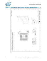
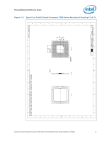
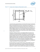
Thermal/Mechanical Reference Design 2.1.2 Quad-Core Intel® Xeon® Processor 5300 Series Package The Quad-Core Intel® Xeon® Processor 5300 Series is packaged using the flip-chip land grid array (FC-LGA6) package technology. Please refer to the Quad-Core Intel® Xeon® Processor 5300 Series Datasheet for detailed mechanical specifications. The Quad-Core Intel® Xeon® Processor 5300 Series Mechanical drawing shown in Figure 2-1, Figure 2-2 and Figure 2-3 provide the mechanical information for QuadCore Intel® Xeon® Processor 5300 Series. The stackup height of the processors in the socket is shown in Appendix B. The drawing is superseded with the drawing in the processor Datasheet, should there be any conflicts. Integrated package/socket stackup height information is provided in the LGA771 Socket Mechanical Design Guide. The package includes an integrated heat spreader (IHS). The IHS transfers the nonuniform heat from the die to the top of the IHS, out of which the heat flux is more uniform and spreads over a larger surface area (not the entire IHS area). This allows more efficient heat transfer out of the package to an attached cooling device. The IHS is designed to be the interface for contacting a heatsink. Details can be found in the Quad-Core Intel® Xeon® Processor 5300 Series Datasheet. The processor connects to the baseboard through a 771-land surface mount socket. A description of the socket can be found in the LGA771 Socket Mechanical Design Guide. The processor package and socket have mechanical load limits that are specified in the Quad-Core Intel® Xeon® Processor 5300 Series Datasheet and the LGA771 Socket Mechanical Design Guide. These load limits should not be exceeded during heatsink installation, removal, mechanical stress testing, or standard shipping conditions. For example, when a compressive static load is necessary to ensure thermal performance of the Thermal Interface Material (TIM) between the heatsink base and the IHS, it should not exceed the corresponding specification given in the LGA771 Socket Mechanical Design Guide. The heatsink mass can also add additional dynamic compressive load to the package during a mechanical shock event. Amplification factors due to the impact force during shock must be taken into account in dynamic load calculations. The total combination of dynamic and static compressive load should not then exceed the processor/socket compressive dynamic load specified in the LGA771 Socket Mechanical Design Guide during a vertical shock. It is not recommended to use any portion of the processor substrate as a mechanical reference or load-bearing surface in either static or dynamic compressive load conditions. 14 Quad-Core Intel® Xeon® Processor 5300 Series Thermal/Mechanical Design Guidelines (TMDG)
-
 1
1 -
2
-
3
-
4
-
5
-
6
-
7
-
8
-
 9
9 -
 10
10 -
 11
11 -
 12
12 -
 13
13 -
 14
14 -
 15
15 -
 16
16 -
 17
17 -
 18
18 -
 19
19 -
20
-
21
-
22
-
23
-
24
-
25
-
26
-
27
-
28
-
29
-
30
-
31
-
32
-
33
-
34
-
35
-
36
-
37
-
38
-
39
-
40
-
41
-
42
-
43
-
44
-
45
-
46
-
47
-
48
-
49
-
50
-
51
-
52
-
53
-
54
-
55
-
56
-
57
-
58
-
59
-
60
-
61
-
62
-
63
-
64
-
65
-
66
-
67
-
68
-
69
-
70
-
71
-
72
-
73
-
74
-
75
-
76
-
77
-
78
-
79
-
80
-
81
-
82
-
83
-
84
-
85
-
86
-
87
-
88
-
89
-
90
-
91
-
92
-
93
-
94
-
95
-
96
-
97
-
98
-
99
-
100
 |
 |
