Intel X5365 Design Guide - Page 18
Quad-Core Intel® Xeon® Processor 5300 Series Considerations
 |
UPC - 735858199292
View all Intel X5365 manuals
Add to My Manuals
Save this manual to your list of manuals |
Page 18 highlights
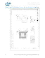
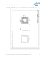
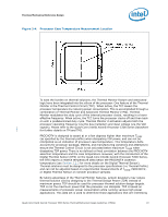
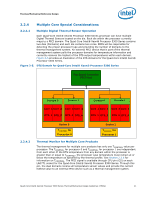
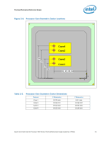
Thermal/Mechanical Reference Design 2.1.3 Note: 2.2 2.2.1 Quad-Core Intel® Xeon® Processor 5300 Series Considerations An attachment mechanism must be designed to support the heatsink since there are no features on the LGA771 socket to directly attach a heatsink. In addition to holding the heatsink in place on top of the IHS, this mechanism plays a significant role in the robustness of the system in which it is implemented, in particular: • Ensuring thermal performance of the TIM applied between the IHS and the heatsink. TIMs, especially ones based on phase change materials, are very sensitive to applied pressure: the higher the pressure, the better the initial performance. TIMs such as thermal greases are not as sensitive to applied pressure. Refer to Section 2.4.2 and Section 2.4.7.2 for information on tradeoffs made with TIM selection. Designs should consider possible decrease in applied pressure over time due to potential structural relaxation in enabled components. • Ensuring system electrical, thermal, and structural integrity under shock and vibration events. The mechanical requirements of the attach mechanism depend on the weight of the heatsink and the level of shock and vibration that the system must support. The overall structural design of the baseboard and system must be considered when designing the heatsink attach mechanism. Their design should provide a means for protecting LGA771 socket solder joints as well as preventing package pullout from the socket. The load applied by the attachment mechanism must comply with the package and socket specifications, along with the dynamic load added by the mechanical shock and vibration requirements, as identified in Section 2.1.1. A potential mechanical solution for heavy heatsinks is the direct attachment of the heatsink to the chassis pan. In this case, the strength of the chassis pan can be utilized rather than solely relying on the baseboard strength. In addition to the general guidelines given above, contact with the baseboard surfaces should be minimized during installation in order to avoid any damage to the baseboard. The Intel reference design for Quad-Core Intel® Xeon® Processor 5300 Series is using such a heatsink attachment scheme. Refer to Section 2.4 for further information regarding the Intel reference mechanical solution. Processor Thermal Parameters and Features Thermal Control Circuit and TDP The operating thermal limits of the processor are defined by the Thermal Profile. The intent of the Thermal Profile specification is to support acoustic noise reduction through fan speed control and ensure the long-term reliability of the processor. This specification requires that the temperature at the center of the processor IHS, known as (TCASE) remains within a certain temperature specification. For illustration, Figure 2-4 shows the measurement location for the Quad-Core Intel® Xeon® Processor 5300 Series package. Compliance with the TCASE specification is required to achieve optimal operation and long-term reliability (See the Intel® Xeon® Dual and Multi Processor Family Thermal Test Vehicle User's Guide for Case Temperature definition and measurement methods). 18 Quad-Core Intel® Xeon® Processor 5300 Series Thermal/Mechanical Design Guidelines (TMDG)
-
 1
1 -
2
-
3
-
4
-
5
-
6
-
7
-
8
-
9
-
10
-
11
-
12
-
 13
13 -
 14
14 -
 15
15 -
 16
16 -
 17
17 -
 18
18 -
 19
19 -
 20
20 -
 21
21 -
 22
22 -
 23
23 -
24
-
25
-
26
-
27
-
28
-
29
-
30
-
31
-
32
-
33
-
34
-
35
-
36
-
37
-
38
-
39
-
40
-
41
-
42
-
43
-
44
-
45
-
46
-
47
-
48
-
49
-
50
-
51
-
52
-
53
-
54
-
55
-
56
-
57
-
58
-
59
-
60
-
61
-
62
-
63
-
64
-
65
-
66
-
67
-
68
-
69
-
70
-
71
-
72
-
73
-
74
-
75
-
76
-
77
-
78
-
79
-
80
-
81
-
82
-
83
-
84
-
85
-
86
-
87
-
88
-
89
-
90
-
91
-
92
-
93
-
94
-
95
-
96
-
97
-
98
-
99
-
100
 |
 |
