Intel X5365 Design Guide - Page 19
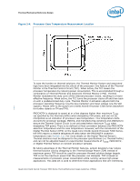
Processor Case Temperature Measurement Location
 |
UPC - 735858199292
View all Intel X5365 manuals
Add to My Manuals
Save this manual to your list of manuals |
Page 19 highlights
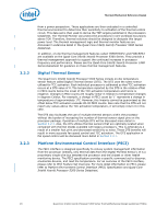
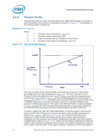
Thermal/Mechanical Reference Design Figure 2-4. Processor Case Temperature Measurement Location To ease the burden on thermal solutions, the Thermal Monitor feature and associated logic have been integrated into the silicon of the processor. One feature of the Thermal Monitor is the Thermal Control Circuit (TCC). When active, the TCC lowers the processor temperature by reducing power consumption. This is accomplished through a combination of Thermal Monitor and Advanced Thermal Monitor (TM2). Thermal Monitor modulates the duty cycle of the internal processor clocks, resulting in a lower effective frequency. When active, the TCC turns the processor clocks off and then back on with a predetermined duty cycle. Thermal Monitor 2 activation adjusts both the processor operating frequency (via the bus multiplier) and input voltage (via the VID signals). Please refer to the Quad-Core Intel® Xeon® Processor 5300 Series Datasheet for further details on TM and TM2. PROCHOT# is designed to assert at or a few degrees higher than maximum TCASE (as specified by the thermal profile) when dissipating TDP power, and can not be interpreted as an indication of processor case temperature. This temperature delta accounts for processor package, lifetime, and manufacturing variations and attempts to ensure the Thermal Control Circuit is not activated below maximum TCASE when dissipating TDP power. There is no defined or fixed correlation between the PROCHOT# assertion temperature and the case temperature. However, with the introduction of the Digital Thermal Sensor (DTS) on the Quad-Core Intel® Xeon® Processor 5300 Series, the DTS reports a relative temperature delta below the PROCHOT# assertion temperature (see Section 2.2.2 for more details on the Digital Thermal Sensor). Thermal solutions must be designed to the processor specifications (i.e Thermal Profile) and can not be adjusted based on experimental measurements of TCASE, PROCHOT#, or Digital Thermal Sensor on random processor samples. By taking advantage of the Thermal Monitor features, system designers may reduce thermal solution cost by designing to the Thermal Design Power (TDP) instead of maximum power. TDP should be used for processor thermal solution design targets. TDP is not the maximum power that the processor can dissipate. TDP is based on measurements of processor power consumption while running various high power applications. This data set is used to determine those applications that are interesting Quad-Core Intel® Xeon® Processor 5300 Series Thermal/Mechanical Design Guidelines (TMDG) 19
-
 1
1 -
2
-
3
-
4
-
5
-
6
-
7
-
8
-
9
-
10
-
11
-
12
-
13
-
 14
14 -
 15
15 -
 16
16 -
 17
17 -
 18
18 -
 19
19 -
 20
20 -
 21
21 -
 22
22 -
 23
23 -
 24
24 -
25
-
26
-
27
-
28
-
29
-
30
-
31
-
32
-
33
-
34
-
35
-
36
-
37
-
38
-
39
-
40
-
41
-
42
-
43
-
44
-
45
-
46
-
47
-
48
-
49
-
50
-
51
-
52
-
53
-
54
-
55
-
56
-
57
-
58
-
59
-
60
-
61
-
62
-
63
-
64
-
65
-
66
-
67
-
68
-
69
-
70
-
71
-
72
-
73
-
74
-
75
-
76
-
77
-
78
-
79
-
80
-
81
-
82
-
83
-
84
-
85
-
86
-
87
-
88
-
89
-
90
-
91
-
92
-
93
-
94
-
95
-
96
-
97
-
98
-
99
-
100
 |
 |
