Intel X5365 Design Guide - Page 20
Digital Thermal Sensor, 2.2.3 Platform Environmental Control Interface (PECI)
 |
UPC - 735858199292
View all Intel X5365 manuals
Add to My Manuals
Save this manual to your list of manuals |
Page 20 highlights
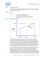
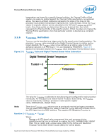
Thermal/Mechanical Reference Design 2.2.2 2.2.3 from a power perspective. These applications are then evaluated in a controlled thermal environment to determine their sensitivity to activation of the thermal control circuit. This data set is then used to derive the TDP targets published in the processors Datasheet. The Thermal Monitor can protect the processors in rare workload excursions above TDP. Therefore, thermal solutions should be designed to dissipate this target power level. The thermal management logic and thermal monitor features are discussed in extensive detail in the Quad-Core Intel® Xeon® Processor 5300 Series Datasheet. In addition, on-die thermal management features called THERMTRIP# and FORCEPR# are available on the Quad-Core Intel® Xeon® Processor 5300 Series. They provide a thermal management approach to support the continued increases in processor frequency and performance. Please see the Quad-Core Intel® Xeon® Processor 5300 Series Datasheet for guidance on these thermal management features. Digital Thermal Sensor The Quad-Core Intel® Xeon® Processor 5300 Series include on-die temperature sensor feature called Digital Thermal Sensor (DTS). The DTS uses the same sensor utilized for TCC activation. Each individual processor is calibrated so that TCC activation occurs at a DTS value of 0. The temperature reported by the DTS is the relative offset in PECI counts below the onset of the TCC activation temperature and hence is negative. Changes in PECI counts are roughly linear in relation to temperature changes in degrees Celsius. For example, a change in PECI count by '1' represents a change in temperature of approximately 1°C. However, this linearity cannot be guaranteed as the offset below TCC activation exceeds 20-30 PECI counts. Also note that the DTS will not report any values above the TCC activation temperature, it will simply return 0 in this case. The DTS also facilitates the use of multiple thermal sensors within the processor without the burden of increasing the number of thermal sensor signal pins on the processor package. Operation of multiple DTS will be discussed more detail in Section 2.2.4. Also, the DTS utilizes thermal sensors that are optimally located when compared with thermal diodes available with legacy processors. This is achieved as a result of a smaller foot print and decreased sensitivity to noise. These DTS benefits will result in more accurate fan speed control and TCC activation. The DTS application in fan speed control will be discussed more detail in Section 2.3.1. Platform Environmental Control Interface (PECI) The PECI interface is designed specifically to convey system management information from the processor (initially, only thermal data from the Digital Thermal Sensor). It is a proprietary single wire bus between the processor and the chipset or other health monitoring device. The PECI specification provides a specific command set to discover, enumerate devices, and read the temperature. For an overview of the PECI interface, please refer to PECI Feature Set Overview. For more detail information on PECI, please refer to Platform Environment Control Interface (PECI) Specification and Quad-Core Intel® Xeon® Processor 5300 Series Datasheet. 20 Quad-Core Intel® Xeon® Processor 5300 Series Thermal/Mechanical Design Guidelines (TMDG)
-
 1
1 -
2
-
3
-
4
-
5
-
6
-
7
-
8
-
9
-
10
-
11
-
12
-
13
-
14
-
 15
15 -
 16
16 -
 17
17 -
 18
18 -
 19
19 -
 20
20 -
 21
21 -
 22
22 -
 23
23 -
 24
24 -
 25
25 -
26
-
27
-
28
-
29
-
30
-
31
-
32
-
33
-
34
-
35
-
36
-
37
-
38
-
39
-
40
-
41
-
42
-
43
-
44
-
45
-
46
-
47
-
48
-
49
-
50
-
51
-
52
-
53
-
54
-
55
-
56
-
57
-
58
-
59
-
60
-
61
-
62
-
63
-
64
-
65
-
66
-
67
-
68
-
69
-
70
-
71
-
72
-
73
-
74
-
75
-
76
-
77
-
78
-
79
-
80
-
81
-
82
-
83
-
84
-
85
-
86
-
87
-
88
-
89
-
90
-
91
-
92
-
93
-
94
-
95
-
96
-
97
-
98
-
99
-
100
 |
 |
