Konica Minolta KIP 75 Series KIP 75 Series Hardware User Manual
Konica Minolta KIP 75 Series Manual
 |
View all Konica Minolta KIP 75 Series manuals
Add to My Manuals
Save this manual to your list of manuals |
Konica Minolta KIP 75 Series manual content summary:
- Konica Minolta KIP 75 Series | KIP 75 Series Hardware User Manual - Page 1
75 Series User Manual Version A.0 - Konica Minolta KIP 75 Series | KIP 75 Series Hardware User Manual - Page 2
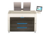
KIP 7570 Series. This Hardware Operation Guide contains functional and operational explanations for the KIP 7570 Series. Please read this Hardware Operation Guide carefully before using the printer. Please keep this Hardware Operation Guide accordance with the instruction manual,, may cause harmful - Konica Minolta KIP 75 Series | KIP 75 Series Hardware User Manual - Page 3
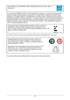
KIP 7570 Series is an ENERGY STAR qualified Wide Format Printer / MFP equipment. The International ENERGY STAR ® Office Equipment Program is an international program that promotes energy saving - Konica Minolta KIP 75 Series | KIP 75 Series Hardware User Manual - Page 4
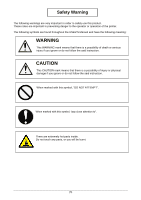
of the printer. The following symbols are found throughout the USER'S Manual and have the following meaning: WARNING This WARNING mark means that there injury or physical damage if you ignore or do not follow the said instruction. When marked with this symbol, "DO NOT ATTEMPT". When marked with this - Konica Minolta KIP 75 Series | KIP 75 Series Hardware User Manual - Page 5
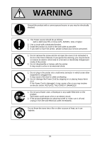
move the printer, please contact your service personnel. 1. Do not remove the screw and do not open the cover if not instructed to do so in this User's Manual. If you ignore this warning, outlet immediately. Do not throw the toner into a fire or other sources of heat, as it can explode. (4) - Konica Minolta KIP 75 Series | KIP 75 Series Hardware User Manual - Page 6
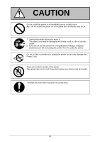
CAUTION Do not install the printer in a humidified room or a dusty room. Also, do not install the printer on an unstable floor as injuries may occur. 1. Unplug the printer before you move it. The power cord may be damaged and it may result in a fire or electric shock. 2. If you do not use the - Konica Minolta KIP 75 Series | KIP 75 Series Hardware User Manual - Page 7
POWER CORD INSTRUCTION The installation of (or exchange to) a power plug which fits in the wall outlet of the installation location shall be conducted in accordance with the - Konica Minolta KIP 75 Series | KIP 75 Series Hardware User Manual - Page 8
Chapter 1 Before Use . 1. 1 Installation Requirements 1. 2 Originals Prohibited from Duplication 1. 3 Features 1. 4 Specifications 1. 4. 1 General 1. 4. 2 Printer Part 1. 4. 3 Scanner part (for MFP Model) 1. 5 Appearance 1. 5. 1 Front view 1. 5. 2 Rear view 1. 6 Specifications for Scan Original ( - Konica Minolta KIP 75 Series | KIP 75 Series Hardware User Manual - Page 9
and the floor strength must be ample to sustain the weight of the equipment. (Rear) 30cm/12" or larger 720mm / 29" KIP 7570 Series L* 1560mm / 62" R* (Front) 80cm/32" or larger * L + R = 35cm/14" or larger (R must be larger than L) (L = 5cm/2" or larger recommended) 1-2 Chapter 1 Before - Konica Minolta KIP 75 Series | KIP 75 Series Hardware User Manual - Page 10
1. 2 Originals Prohibited from Duplication It is not necessarily allowed to copy every kind of original. You may be punished by the law if only you possess the copy of some kind of original. We recommend you to consider enough before you copy such original. [Originals prohibited from copying by the - Konica Minolta KIP 75 Series | KIP 75 Series Hardware User Manual - Page 11
Features (1) KIP 75 Series is an Electro Photographic wide format LED printer/MFP. Advanced drivers and comprehensive print utilities make the KIP 75 an advanced rolls wide format printer model (3) KIP HDP technology generates no waste toner. (4) The KIP HDP Plus imaging system produces high - Konica Minolta KIP 75 Series | KIP 75 Series Hardware User Manual - Page 12
consumption (Maximum) Power consumption (Low power mode) Acoustic noise Ozone Dimensions Weight Environmental condition for usage Interface Rating Specification KIP 75 Series Wide Format MFP with 2 Roll / 4 Roll Wide Format Printer with 2 Roll / 4 Roll Console 3120W or less (scanner / controller - Konica Minolta KIP 75 Series | KIP 75 Series Hardware User Manual - Page 13
feeding method Warm up time First print time Fusing method Development method 2 Roll Decks / 4 Roll Decks Manual Feeder (single cut sheet) Shorter than 4 minutes (At 23oC, 60%RH, the rated voltage, and ) Heat and Pressure Rollers Dry type non-magnetic mono-component toner 1-6 Chapter 1 Before Use - Konica Minolta KIP 75 Series | KIP 75 Series Hardware User Manual - Page 14
Subject Media Storage of consumables Specification (Recommended Media) US model: Bond Vellum Film EU / Asia model: Plain Paper Tracing Paper Film (Toner cartridge) Store the cartridge within the temperature range from 0 to 35 degrees Centigrade and within the humidity range from 35 to 85% RH. NOTE - Konica Minolta KIP 75 Series | KIP 75 Series Hardware User Manual - Page 15
1. 4. 3 Scanner part (for MFP Model) Subject Scanning method Light source Scanning speed (600 dpi, normal quality) (max) Specification Contact Image Sensor (CIS) (5 pieces of A4 sized CIS) LED (R/G/B) Monochrome : 65mm/s Grayscale : 65mm/s Color : 22mm/s Setting of original Starting point - Konica Minolta KIP 75 Series | KIP 75 Series Hardware User Manual - Page 16
Appearance 1. 5. 1 Front view 11 12 11 6 2 7 8 9 10 4 5 3 13 2 1 8 No. Name 1 Main Switch 2 Original Guides 3 User Interface 4 Scan Abort Button 5 Start Button 6 Scanner Unit (MFP Model Only) 7 Toner Hatch (Original Table) 8 Engine Unit Open Lever 9 Bypass Feeder 10 Roll Deck 11 Print Tray - Konica Minolta KIP 75 Series | KIP 75 Series Hardware User Manual - Page 17
Door when you remove the paper misfed inside the Fuser Unit. Connect the LAN Cable to connect the KIP 7570 to the network. (Do not connect a telephone line) Turn on the Dehumidify Heater with this Connect the Power Cord here. For an optional device Service Use. 5VDC max. 1-10 Chapter 1 Before Use - Konica Minolta KIP 75 Series | KIP 75 Series Hardware User Manual - Page 18
1. 6 Specifications for Scan Original (for MFP Model) A scan original must satisfy the following specifications. Thickness Width Length 0.05mm to 1.60mm 210mm to 914.4mm 210mm to 6,000mm NOTE : 1. Suggest to change "It does not guarantee both scan/copy image quality and original feeding - Konica Minolta KIP 75 Series | KIP 75 Series Hardware User Manual - Page 19
1. 6. 3 "Do Not Scan" Originals It is impossible to use the following types of originals because they are likely to damage the scanner. Do not scan the following kinds of original, because you may damage the original or scanner itself! Sticked with paste Paste Torn Folded (Leading edge) So much - Konica Minolta KIP 75 Series | KIP 75 Series Hardware User Manual - Page 20
Not square Wet image Made of metal or fabric Rough surface (Carbon paper for example) Clipped or stapled Metal Wet Fabric Rough surface Clipped Stapled 1-13 Chapter 1 Before Use - Konica Minolta KIP 75 Series | KIP 75 Series Hardware User Manual - Page 21
The following kinds of originals can be read with using a carrier sheet. However, the image quality and feed reliability are not guaranteed. Patched Punched 1-14 Chapter 1 Before Use - Konica Minolta KIP 75 Series | KIP 75 Series Hardware User Manual - Page 22
1. 7 Specifications for the Printing Media 1. 7. 1 Papers not available to use Do not use the following kinds of printing paper. Doing so may damage the print engine. Excessively curled (a diameter of 50 mm or less) Folded Creased Torn Punched 1-15 Chapter 1 Before Use - Konica Minolta KIP 75 Series | KIP 75 Series Hardware User Manual - Page 23
Pre-printed Extremely slippery Extremely sticky Extremely thin and soft OHP Film CAUTION Do not use the paper with staple, or do not use such conductive paper as aluminium foil and carbon paper. The above may result in a danger of fire. NOTE (1) Print image may become light if printed on a rough - Konica Minolta KIP 75 Series | KIP 75 Series Hardware User Manual - Page 24
tracing paper. "Void of image" occurs when you print with plain paper and tracing paper. "Void of image", "crease of paper" and other problems occurs when you print with plain paper and tracing paper. Necessary treatment 1. Install the humidifier in the room, and humidify the room air. 2. Remove - Konica Minolta KIP 75 Series | KIP 75 Series Hardware User Manual - Page 25
Chapter 2 Basic Operation 2. 1 Turning on the Printer 2. 2 Turning off the Printer 2. 3 Replacing Roll Media 2. 4 Replacing Toner Cartridge 2. 5 Cut Sheet Media 2. 6 Copying (for MFP Model) 2. 7 Stop of Scan or Copy (for MFP Model) 2. 8 Dehumidifying Roll Media 2-1 Page 2- 2 2- 4 2- 5 2-11 2-16 2- - Konica Minolta KIP 75 Series | KIP 75 Series Hardware User Manual - Page 26
2. 1 Turning on the Printer 1. Plug the power cord for Printer into a dedicated wall outlet. WARNING (1) Do not handle the Power Plug with wet hands, or you may receive an electrical shock. (2) Make sure to earth the machine for safety. (3) Do not plug the printer into a multi-wiring connector in - Konica Minolta KIP 75 Series | KIP 75 Series Hardware User Manual - Page 27
3. The User Interface (UI) starts operating, and displays the following Copy Mode Screen in one minute. "Warming Up" is displayed in the status indication while warming up. The UI screen may vary depending on your system configuration. (Shown with available options) NOTE It is not possible to print - Konica Minolta KIP 75 Series | KIP 75 Series Hardware User Manual - Page 28
2. 2 Turning off the Printer 1. There is a Power Switch on the right side of Printer. Press its " " side to turn off the Printer. Power Switch Press " " side. CAUTION The Printer print engine and UI appear to be shut down when you turn off Printer. However, the controller PC embedded inside the - Konica Minolta KIP 75 Series | KIP 75 Series Hardware User Manual - Page 29
UI Screen will display "Out of Paper" sign. Follow the later procedure (or as noted in the UI's User Guide) to load a roll media. Please refer to your KIP IPS Touch Screen Operator's Guide for the UI screen. (2) This section describes how to install a roll media to Roll Deck 1. The same procedure is - Konica Minolta KIP 75 Series | KIP 75 Series Hardware User Manual - Page 30
Raise the green lever (4) on Flange (2). Remove both Flanges (4) from the roll core (3). 3 4 2 2 4. Move a right Slide Guide (5) to match your roll media's width. The right and left Side Guides will automatically move together. 5: for Roll 2 Size markings 5 5 2-6 Chapter 2 Basic Operation - Konica Minolta KIP 75 Series | KIP 75 Series Hardware User Manual - Page 31
5. Insert each Flange (2) into both ends of the roll media core to be installed. 2 NOTE (1) Fully insert Flange into the roll media core so that the inside rim of Flange evenly touches the side face of the roll media. Inside Rim Inside Rim Gap OK NG Correct: Fully inserted Wrong: not - Konica Minolta KIP 75 Series | KIP 75 Series Hardware User Manual - Page 32
Correct: Edge comes from bottom Wrong: Edge comes from top (2) The outside rim (6) of Flange should meet the black triangle (7) marked on Slide Guide. Otherwise the roll media may fall in Roll Deck or result in an incorrect media feeding. 7 7 6 6 Correct Wrong 2-8 Chapter 2 Basic Operation - Konica Minolta KIP 75 Series | KIP 75 Series Hardware User Manual - Page 33
. 8 8 9 NOTE Use the rear Feed Knob (10) for Roll Deck 2 or Roll Deck 4. 10 9. Hold the green grip (11: on the middle of Guide Plate) and turn Guide Plate outside. With holding, rotate Feed Knob (9) again so that the leading edge comes out in 100mm. Leading edge of roll media 11 9 2-9 Chapter - Konica Minolta KIP 75 Series | KIP 75 Series Hardware User Manual - Page 34
10. Slide the green Cutter Knob (12) fully from one side to the other to make a new straight edge. Remove the cut portion. 12 NOTE Completely slide Cutter Knob (12) until it stops at either end. Not doing so may cause a paper jam. OK NG 12 12 Correct Wrong 11. Gently close Roll Deck. NOTE - Konica Minolta KIP 75 Series | KIP 75 Series Hardware User Manual - Page 35
. Follow the later procedure (or as noted in the UI's User Guide) to replace the Toner Cartridge with a new one (genuine). NOTE (1) The Printer will indicate Toner Empty sign if an incorrect toner cartridge or no toner cartridge is installed to the printer. (2) At the machine's installation, some - Konica Minolta KIP 75 Series | KIP 75 Series Hardware User Manual - Page 36
2. Slide the green Lever (2) to the right to unlock the Toner Cartridge. (Lever (2) is held automatically.) 2 NOTE Be sure to unlock the Toner Cartridge by releasing the green Lever (2). 2 2 OK Correct: disengaged (The green Lever (2) is shifted to the right.) NG Wrong: not disengaged 2-12 - Konica Minolta KIP 75 Series | KIP 75 Series Hardware User Manual - Page 37
Cartridge Lock Lever (3), turn the body (4) of cartridge to the arrow direction until it stops. (You can close the toner supply hole of the cartridge firmly by this) 4 3 NOTE The toner may drop from the toner supply hole, and it may scattered into the machine or on the floor if you remove the - Konica Minolta KIP 75 Series | KIP 75 Series Hardware User Manual - Page 38
Side 6. Keep pressing down the Cartridge Lock Lever (3). Direct the toner supply hole to the floor, fit the pin (6) on the left NOTE Please confirm that the Cartridge Lock Lever (3) firmly locks the Toner Cartridge at the correct position. (It must be at a level position.) 3 3 OK NG - Konica Minolta KIP 75 Series | KIP 75 Series Hardware User Manual - Page 39
7. Turn the body (4) of the cartridge in two or more revolution to the arrow direction to open the toner supply hole. Confirm that the projection (8) if fitted into the notch (9). 4 8 9 NOTE It is not necessary to lock the cartridge with the Lever (2). Lever (2) will - Konica Minolta KIP 75 Series | KIP 75 Series Hardware User Manual - Page 40
2. 5 Cut Sheet Media 1. Open the Bypass Feeder (1). Bypass Feeder 2. There are several size markings on the table of Bypass Feeder which indicate possible feed positions. Place the cut sheet paper on the table between its concerning size markings then insert it into the Bypass Feeder. When the - Konica Minolta KIP 75 Series | KIP 75 Series Hardware User Manual - Page 41
2. There are several size markings on Original Table which indicate possible feed positions. Line up Original Guides with the proper markings according to the original width. Original Guide Original Guide 3. Place the original on the Original Table with face up. Then insert it under the Scanner - Konica Minolta KIP 75 Series | KIP 75 Series Hardware User Manual - Page 42
4. The Printer will start the copy process. Reference Pressing START button may be required to start the scan according to the scanner's controller software. For further details of "Auto Start", see the software's document. Start Button NOTE The scanner unit does not accept originals - Konica Minolta KIP 75 Series | KIP 75 Series Hardware User Manual - Page 43
screen shows "Upper Bin Full", remove all the prints on the print tray. For further information of switching front / back delivery, see Touch screen Operator's Guide. 2-19 Chapter 2 Basic Operation - Konica Minolta KIP 75 Series | KIP 75 Series Hardware User Manual - Page 44
2. 7 Stop of Scan or Copy (for MFP Model) 1. If necessary, press the Scan Abort Button on the Scanner Unit to immediately stop the original while making a copy or scan. The LED Indicator flashes red. red flashing Scan Abort Button Pressing the button stops the current reading a document - Konica Minolta KIP 75 Series | KIP 75 Series Hardware User Manual - Page 45
of roll media, it is recommended to use this kit. Ask your service personnel for DEHUMIDIFY KIT. If the roll paper is extremely humidified, it may if the room air has too much humidity (75% or higher) to prevent the above kinds of print defect. Such problems above may be resolved. To turn on the - Konica Minolta KIP 75 Series | KIP 75 Series Hardware User Manual - Page 46
1. 1 Roll Deck Section Jam (Deck 1, 2 Mis-feed) 3. 1. 2 Manual Feeder Section Jam (Registration Mis-feed) 3. 1. 3 Media Feed Section Jam Model) 3. 3 Other Operator Call 3. 3. 1 Roll Replacement 3. 3. 2 Toner Empty 3. 3. 3 Accessory Error 3. 4 Service Call Error Page 3- 2 3- 3 3- 6 3- 8 3-10 3-14 3- - Konica Minolta KIP 75 Series | KIP 75 Series Hardware User Manual - Page 47
jammed location when displaying " xxxx Mis-feed " is shown below. Manual Feeder Section Media Feed Section Fuser Section Roll Deck Section Roll Deck a jammed paper. When it does not reach Fuser Unit, toner on it may spill off. If toner gets into eyes or your mouth, immediately rinse them with - Konica Minolta KIP 75 Series | KIP 75 Series Hardware User Manual - Page 48
3. 1. 1 Roll Deck Section Jam (Deck 1, 2 Mis-feed) Roll Deck Section - Deck 1 Mis-feed Roll Deck Section - Deck 2 Mis-feed 1. Pull the blue lever (1) to unlock the Roll Deck. Draw out the Roll Deck. 1 2. Rewind the roll media. 3-3 Chapter 3 Error Correction - Konica Minolta KIP 75 Series | KIP 75 Series Hardware User Manual - Page 49
in case of an extreme crease. (2) Use the rear Feed Knob (4) for Roll Deck 2. 4 4. Hold the green grip (5: on the middle of Guide Plate) and turn Guide Plate outside. With holding, rotate Feed Knob (3) again so that the leading edge comes out in 100mm. Leading edge of roll media 5 3 3-4 Chapter - Konica Minolta KIP 75 Series | KIP 75 Series Hardware User Manual - Page 50
5. Slide the green Cutter Knob (6) fully from one side to the other to make a new straight edge. Remove the cut portion. 6 NOTE Completely slide Cutter Knob (6) until it stops at either end. Not doing so may cause a paper jam. OK NG 6 6 6. Gently close Roll Deck. NOTE Be sure to close the - Konica Minolta KIP 75 Series | KIP 75 Series Hardware User Manual - Page 51
3. 1. 2 Manual Feeder Section Jam (Registration Mis-feed) Manual Feeder Section - Registration Mis-feed 1. Remove all Print Trays (1). 1 1 1 2. Pull up the Engine Unit Open Levers (2) to open the Engine Unit. 2 2 3-6 Chapter 3 Error Correction - Konica Minolta KIP 75 Series | KIP 75 Series Hardware User Manual - Page 52
3. Remove the mis-fed paper pulling frontward. 4. Gently close the Engine Unit. mis-fed media NOTE (1) Be sure to close the Engine Unit firmly until it locks at the correct position. (2) The mis-feed cut sheet should be replaced with a new one if its leading edge has a torn or fold. Or it should - Konica Minolta KIP 75 Series | KIP 75 Series Hardware User Manual - Page 53
3. 1. 3 Media Feed Section Jam (Registration Mis-feed, Separation Mis-feed) Media Feed Section - Registration Mis-feed Media Feed Section - Separation Mis-feed 1. Remove all Print Trays (1). 1 1 1 2. Pull up the Engine Unit Open Levers (2) to open the Engine Unit. 2 2 3-8 Chapter 3 Error - Konica Minolta KIP 75 Series | KIP 75 Series Hardware User Manual - Page 54
3. Remove the mis-fed paper. 4. Gently close the Engine Unit. mis-fed media NOTE Be sure to close the Engine Unit firmly until it locks at the correct position. 5. Replace Print Trays in the original position. 1 1 1 3-9 Chapter 3 Error Correction - Konica Minolta KIP 75 Series | KIP 75 Series Hardware User Manual - Page 55
3. 1. 4 Fuser Section Jam (Exit Back Mis-feed) Fuser Section - Exit Back Mis-feed 1. Remove all Print Trays (1). 1 1 1 2. Pull up the Engine Unit Open Levers (2) to open the Engine Unit. 2 2 3-10 Chapter 3 Error Correction - Konica Minolta KIP 75 Series | KIP 75 Series Hardware User Manual - Page 56
get burnt when you touch the printing paper as it may be very hot. NOTE If removed a mis-fed paper inside the Fuser Door, scattered toner can be adhered to the next print. 3-11 Chapter 3 Error Correction - Konica Minolta KIP 75 Series | KIP 75 Series Hardware User Manual - Page 57
get burnt when you touch the printing paper as it may be very hot. NOTE If removed a mis-fed paper inside the Fuser Door, scattered toner can be adhered to the next print. 7. Close Fuser Door (5) and Exit Cover (3). 5 3 3-12 Chapter 3 Error Correction - Konica Minolta KIP 75 Series | KIP 75 Series Hardware User Manual - Page 58
8. Gently close the Engine Unit. NOTE Be sure to close the Engine Unit firmly until it locks at the correct position. 9. Replace Print Trays in the original position. 1 1 1 3-13 Chapter 3 Error Correction - Konica Minolta KIP 75 Series | KIP 75 Series Hardware User Manual - Page 59
3. 1. 5 Stack Jam 1. Remove print(s) on Print Trays. 2. Remove all Print Trays (1). 1 1 1 3. Pull up the Engine Unit Open Levers (2) to open the Engine Unit. 2 2 4. Pull and remove the jammed print to the top. If the print cannot be removed, see [3.1.4 Fuser Jam] for the later procedure of - Konica Minolta KIP 75 Series | KIP 75 Series Hardware User Manual - Page 60
5. Gently close the Engine Unit. NOTE Be sure to close the Engine Unit firmly until it locks at the correct position. 6. Replace Print Trays in the original position. 1 1 1 3-15 Chapter 3 Error Correction - Konica Minolta KIP 75 Series | KIP 75 Series Hardware User Manual - Page 61
3. 1. 6 Original Jam (for MFP Model) The scanner may stop feeding the original in the scanner if the original skews. Pressing Scan Abort Button during scanning also stops the original in the scanner. In both cases, LED Indicator flashes red. red flashing Scan Abort Button 1. Lift up both sides - Konica Minolta KIP 75 Series | KIP 75 Series Hardware User Manual - Page 62
3. 1. 7 Accessory Jam The printing paper is mis-fed in the optional device such as Auto Stacker or Folder. Remove the mis-fed paper making reference to the User's Manual of concerning device. 3-17 Chapter 3 Error Correction - Konica Minolta KIP 75 Series | KIP 75 Series Hardware User Manual - Page 63
3. 2 Door Open "xxxx Open" is displayed in the UI screen when the door in each unit is opened. 3. 2. 1 Roll Deck (Deck 1 Open, Deck 2 Open) Close the Roll Deck securely to clear "Deck 1 Open" or "Deck 2 Open". Roll Deck 3. 2. 2 Engine Unit (Front Cover Open) Close the Engine Unit securely to clear " - Konica Minolta KIP 75 Series | KIP 75 Series Hardware User Manual - Page 64
3. 2. 3 Paper Exit Door (Paper Exit Door Open) Close the Paper Exit Door securely to clear "Paper Exit Door Open". Paper Exit Door 3. 2. 4 Scanner Unit (Scanner feeder open) (for MFP Model) The UI screen shows "Scanner feeder open" if the Scanner Unit is open. (not closed properly) For closing the - Konica Minolta KIP 75 Series | KIP 75 Series Hardware User Manual - Page 65
procedure, see [2.4 Replacing Toner Cartridge]. 3. 3. 3 Accessory Error If your finishing device (Auto Stacker, Folder) has an error, the UI screen of the printer would also show an error message. For clearing errors on such devices, see the concerning device's User's Manual. 3-20 Chapter 3 Error - Konica Minolta KIP 75 Series | KIP 75 Series Hardware User Manual - Page 66
, and its equivalent internal code) on the UI screen. Call the service staff immediately as these problems can be fixed by a well trained technician only. Before calling the service staff, try to turn on/off the Printer. If "Service Call Error" is indicated again, turn off the machine, unplug it - Konica Minolta KIP 75 Series | KIP 75 Series Hardware User Manual - Page 67
Chapter 4 Maintenance 4. 1 Scanner Unit (for MFP Model) 4. 1. 1 Scan Glass, Feed Roller, Guide Plate 4. 1. 2 Sensor 4. 2 Touch Screen 4-1 Page 4- 2 4- 2 4- 5 4- 7 Chapter 4 Maintenance - Konica Minolta KIP 75 Series | KIP 75 Series Hardware User Manual - Page 68
4. 1 Scanner Unit (for MFP Model) 4. 1. 1 Scan Glass, Feed Roller, Guide Plate It is recommended to clean each Scan Glass, Feeding Rollers and Guide Plates as the scan/copy image may become defective if these parts are dirty. NOTE For ease of visual check, this document shows the Upper - Konica Minolta KIP 75 Series | KIP 75 Series Hardware User Manual - Page 69
3. Gently wipe the Scan Glass (2) and Feed Rollers (white) (3) with a soft cloth. Equal mixture of water and neutral detergent can be used. 2 3 NOTE Do not use organic solvent, glass cleaner and anti-static spray for the cleaning. 4. Wipe the Feed Rollers (rubber) (4) with a dry cloth. 5. Wipe - Konica Minolta KIP 75 Series | KIP 75 Series Hardware User Manual - Page 70
6. Wipe the Upper Guide Plate (5) and the Lower Guide Plate (6) with a dry cloth. 5 5 6 7. Gently press Scanner Unit down and firmly close it. NOTE Press down Scanner Unit on both side to close it. Do not close it by pressing only one side down. 4-4 Chapter 4 Maintenance - Konica Minolta KIP 75 Series | KIP 75 Series Hardware User Manual - Page 71
4. 1. 2 Sensor If Sensors are dirty, the original may be detected incorrectly. Perform cleaning or as needed. NOTE For ease of visual check, this document shows the Upper Unit fully open (not actual wide). 1. Turn off the Printer. 2. Lift up both sides (1) of the Scanner Unit. 1 1 4-5 Chapter 4 - Konica Minolta KIP 75 Series | KIP 75 Series Hardware User Manual - Page 72
3. Gently wipe Sensors (2) with a dry cotton bud. 2 2 2 2 2 2 2 NOTE Do not use water, organic solvent, glass cleaner or antistatic spray for cleaning. 4. Gently press Scanner Unit down and firmly close it. NOTE Press down Scanner Unit on both side to close it. Do not close it by pressing - Konica Minolta KIP 75 Series | KIP 75 Series Hardware User Manual - Page 73
4. 2 Touch Screen 1. Wipe the Touch Screen with a dry cloth. NOTE Do not use water, alcohol, organic solvent and glass cleaner for the cleaning. 4-7 Chapter 4 Maintenance - Konica Minolta KIP 75 Series | KIP 75 Series Hardware User Manual - Page 74
WIDE FORMAT PRINTER / WIDE FORMAT MULTI FUNCTION PRINTER KIP 7570 Series Hardware Operation Guide Version A.0 (Issued on May 13, 2016) Published by Katsuragawa Electric Co., Ltd. 21-1 Shimomaruko 4-Chome, Ota-ku, Tokyo 146-8585, Japan Please note that some
-
 1
1 -
 2
2 -
 3
3 -
 4
4 -
 5
5 -
 6
6 -
 7
7 -
8
-
9
-
10
-
11
-
12
-
13
-
14
-
15
-
16
-
17
-
18
-
19
-
20
-
21
-
22
-
23
-
24
-
25
-
26
-
27
-
28
-
29
-
30
-
31
-
32
-
33
-
34
-
35
-
36
-
37
-
38
-
39
-
40
-
41
-
42
-
43
-
44
-
45
-
46
-
47
-
48
-
49
-
50
-
51
-
52
-
53
-
54
-
55
-
56
-
57
-
58
-
59
-
60
-
61
-
62
-
63
-
64
-
65
-
66
-
67
-
68
-
69
-
70
-
71
-
72
-
73
-
74
 |
 |
75 Series
User Manual
Version A.
0