Konica Minolta KIP 75 Series KIP 75 Series Hardware User Manual - Page 16
Appearance, 1. 5. 1 Front view, Front view
 |
View all Konica Minolta KIP 75 Series manuals
Add to My Manuals
Save this manual to your list of manuals |
Page 16 highlights
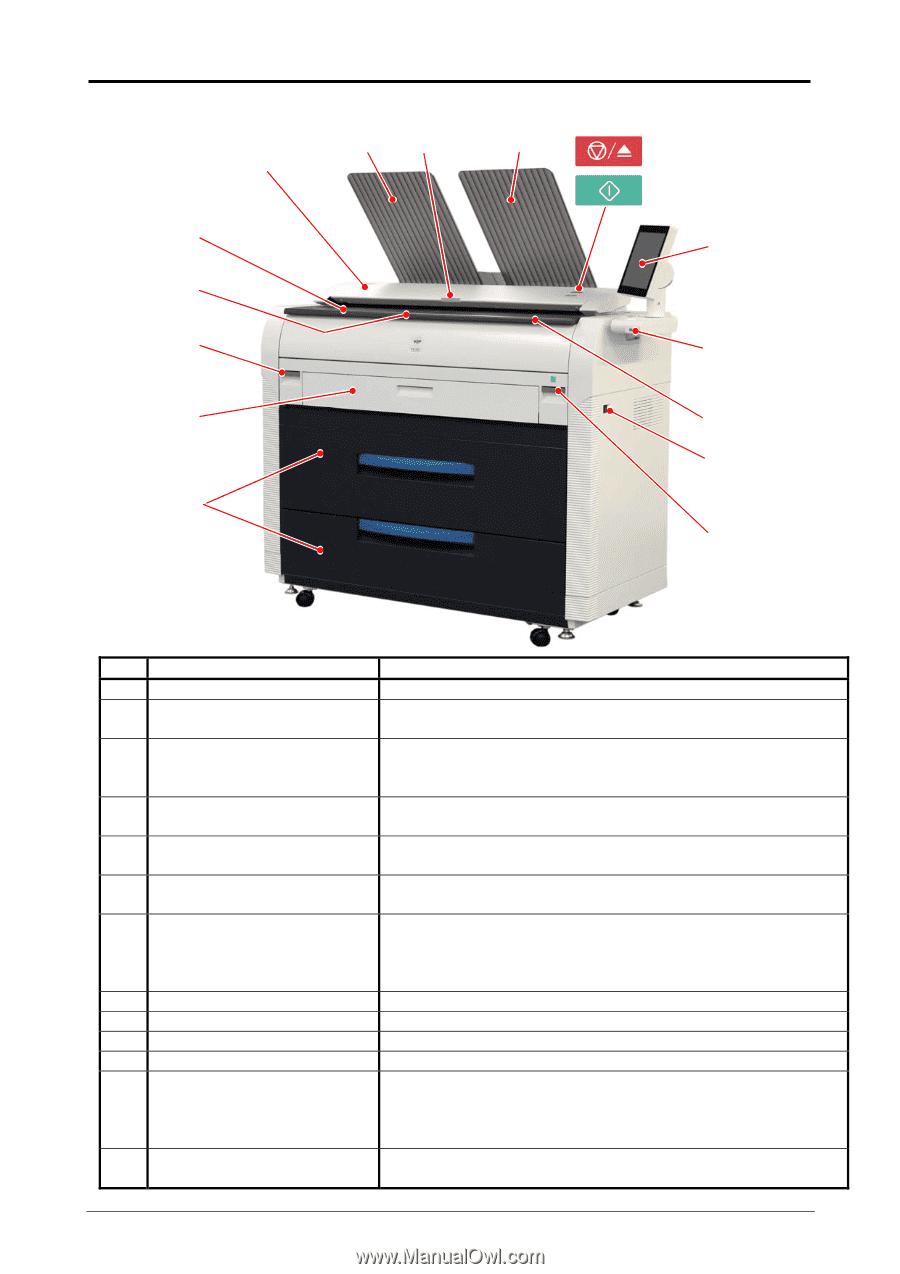
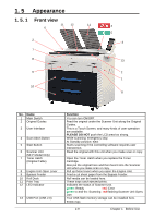
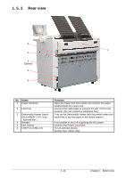
1. 5 Appearance 1. 5. 1 Front view 11 12 11 6 2 7 8 9 10 4 5 3 13 2 1 8 No. Name 1 Main Switch 2 Original Guides 3 User Interface 4 Scan Abort Button 5 Start Button 6 Scanner Unit (MFP Model Only) 7 Toner Hatch (Original Table) 8 Engine Unit Open Lever 9 Bypass Feeder 10 Roll Deck 11 Print Tray 12 LED Indicator 13 USB Port (USB 2.0) Function You can turn ON/OFF. Feed the original under the Scanner Unit along the Original Guides. This is a Touch Screen, and many kinds of user operation are available. PLEASE DO NOT push the LCD area too strong. While scanning: emergency stop At Standby position: eject Starts scanning if the controlling software requires user intervention. Read the original with this unit when you make scan or copy. Open the Toner Hatch when you replace the Toner Cartridge. Also put the original here and then feed it into the Scanner Unit when you make scan or copy. Pull up these levers when you open the Engine Unit. Feed a cut sheet paper from the Bypass Feeder. Roll media can be loaded here. These trays catch ejected prints. Indicates the status of Scanner Unit. green: Ready red: Error green to-and-fro: Scanning red flashing:Scanner Unit Open, Jam Your USB flash memory storage can be installed here. 5VDC max. 1-9 Chapter 1 Before Use
-
 1
1 -
2
-
3
-
4
-
5
-
6
-
7
-
8
-
9
-
10
-
 11
11 -
 12
12 -
 13
13 -
 14
14 -
 15
15 -
 16
16 -
 17
17 -
 18
18 -
 19
19 -
 20
20 -
 21
21 -
22
-
23
-
24
-
25
-
26
-
27
-
28
-
29
-
30
-
31
-
32
-
33
-
34
-
35
-
36
-
37
-
38
-
39
-
40
-
41
-
42
-
43
-
44
-
45
-
46
-
47
-
48
-
49
-
50
-
51
-
52
-
53
-
54
-
55
-
56
-
57
-
58
-
59
-
60
-
61
-
62
-
63
-
64
-
65
-
66
-
67
-
68
-
69
-
70
-
71
-
72
-
73
-
74
 |
 |