Kyocera FS 1100 Service Manual - Page 104
Paper exit Upper FD roller
 |
View all Kyocera FS 1100 manuals
Add to My Manuals
Save this manual to your list of manuals |
Page 104 highlights
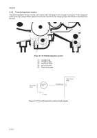
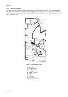
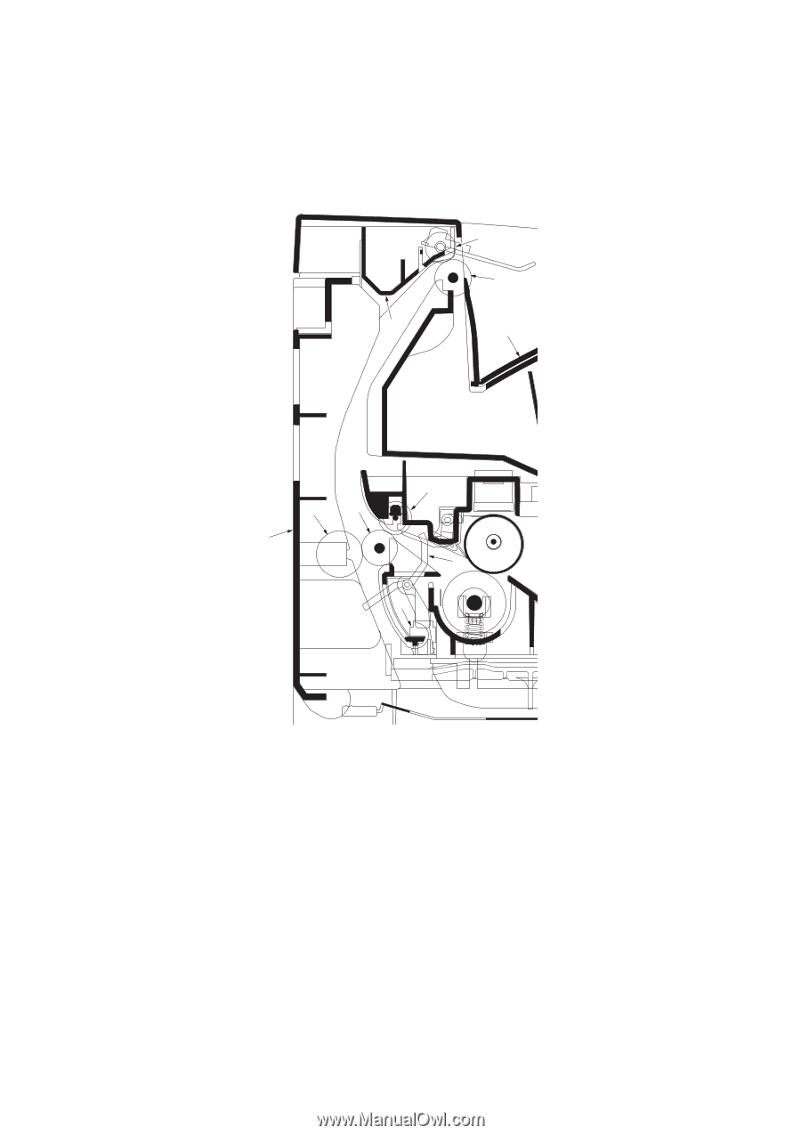
2H5/2HS 2-1-8 Paper exit section The paper exit section transports the paper which passed the fuser unit towards the top tray. The paper which passed through the fuser unit turns on the actuator (exit sensor) in the fuser unit, and is led by the guide comprised of the rear cover, frame and the FD cover guide, finally reaching the upper FD roller. The paper is delivered to the top tray by the rotation of the upper FD roller. 6 5 7 8 2-1-14 3 4 2 1 10 9 Figure 2-1-22 Paper exit section (1) Exit roller (2) Fuser exit pulley (3) Middle pulley (4) Rear cover (5) Upper FD roller (6) Exit pulley (7) FD cover (8) Top tray (9) Exit sensor (10) Actuator (exit sensor)
-
 1
1 -
2
-
3
-
4
-
5
-
6
-
7
-
8
-
9
-
10
-
11
-
12
-
13
-
14
-
15
-
16
-
17
-
18
-
19
-
20
-
21
-
22
-
23
-
24
-
25
-
26
-
27
-
28
-
29
-
30
-
31
-
32
-
33
-
34
-
35
-
36
-
37
-
38
-
39
-
40
-
41
-
42
-
43
-
44
-
45
-
46
-
47
-
48
-
49
-
50
-
51
-
52
-
53
-
54
-
55
-
56
-
57
-
58
-
59
-
60
-
61
-
62
-
63
-
64
-
65
-
66
-
67
-
68
-
69
-
70
-
71
-
72
-
73
-
74
-
75
-
76
-
77
-
78
-
79
-
80
-
81
-
82
-
83
-
84
-
85
-
86
-
87
-
88
-
89
-
90
-
91
-
92
-
93
-
94
-
95
-
96
-
97
-
98
-
 99
99 -
 100
100 -
 101
101 -
 102
102 -
 103
103 -
 104
104 -
 105
105 -
 106
106 -
 107
107 -
 108
108 -
 109
109 -
110
-
111
-
112
-
113
-
114
-
115
-
116
-
117
-
118
-
119
-
120
-
121
-
122
-
123
-
124
 |
 |
2H5/2HS
2-1-14
2-1-8
Paper exit section
The paper exit section transports the paper which passed the fuser unit towards the top tray. The paper which passed
through the fuser unit turns on the actuator (exit sensor) in the fuser unit, and is led by the guide comprised of the rear
cover, frame and the FD cover guide, finally reaching the upper FD roller. The paper is delivered to the top tray by the rota-
tion of the upper FD roller.
Figure 2-1-22 Paper exit section
3
4
10
5
8
7
6
1
9
2
(1)
Exit roller
(2)
Fuser exit pulley
(3)
Middle pulley
(4)
Rear cover
(5)
Upper FD roller
(6)
Exit pulley
(7)
FD cover
(8)
Top tray
(9)
Exit sensor
(10)
Actuator (exit sensor)