2H5/2HS-1
(1) Detaching and refitting the fuser unit
...............................................................................................
1-5-16
(2) Switching the fuser pressure
...........................................................................................................
1-5-18
1-5-8 PWBs
....................................................................................................................................................
1-5-19
(1) Detaching and refitting the control PWB
.........................................................................................
1-5-19
(2) Detaching and refitting the power source PWB
...............................................................................
1-5-22
(3) Detaching and refitting the operation panel PWB
...........................................................................
1-5-24
(4) Detaching and refitting the high voltage PWB
.................................................................................
1-5-25
1-5-9 Others
...................................................................................................................................................
1-5-29
(1) Detaching and refitting the main motor
...........................................................................................
1-5-29
(2) Detaching and refitting the laser scanner unit
.................................................................................
1-5-30
(3) Detaching and refitting the eraser lamp
..........................................................................................
1-5-32
(4) Direction of installing the left and right cooling fan motors
..............................................................
1-5-33
1-6 Firmware
1-6-1
Downloading firmware
............................................................................................................................
1-6-1
(1) Downloading the firmware from the memory card
.............................................................................
1-6-2
2-1 Mechanical Construction
2-1-1
Paper feed/conveying section
.................................................................................................................
2-1-1
(1) Cassette paper feed section
..............................................................................................................
2-1-1
(2) MP tray paper feed section
...............................................................................................................
2-1-2
(3) Paper conveying section
...................................................................................................................
2-1-4
2-1-2
Drum section
...........................................................................................................................................
2-1-5
(1) Drum section
.....................................................................................................................................
2-1-5
(2) Main charger unit
...............................................................................................................................
2-1-6
2-1-3
Expose section
........................................................................................................................................
2-1-7
(1) Laser scanner unit
.............................................................................................................................
2-1-7
2-1-4
Developing section
..................................................................................................................................
2-1-9
2-1-5
Transfer/separation section
..................................................................................................................
2-1-10
2-1-6
Cleaning section
...................................................................................................................................
2-1-11
2-1-7
Fuser section
........................................................................................................................................
2-1-12
2-1-8
Paper exit section
.................................................................................................................................
2-1-14
2-1-9
Duplex/conveying section (duplex model only)
.....................................................................................
2-1-16
2-2 Electrical Parts Layout
2-2-1
Electrical parts layout
..............................................................................................................................
2-2-1
(1) PWBs
................................................................................................................................................
2-2-1
(2) Switches and sensors
.......................................................................................................................
2-2-3
(3) Other electrical components
..............................................................................................................
2-2-4
2-3 Operation of the PWBs
2-3-1
Power source PWB
.................................................................................................................................
2-3-1
2-3-2
Control PWB
...........................................................................................................................................
2-3-3
2-4 Appendixes
2-4-1 Appendixes
.............................................................................................................................................
2-4-1
(1) Wiring diagram
..................................................................................................................................
2-4-1
(2) Repetitive defects gauge
...................................................................................................................
2-4-3
(3) Self diagnostic codes indication (Animation)
.....................................................................................
2-4-4
 1
1 7
7 8
8 9
9 10
10 11
11 12
12 13
13 14
14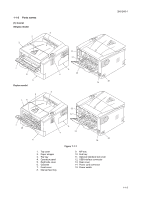 15
15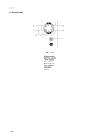 16
16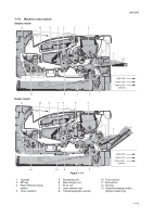 17
17