Kyocera FS 1100 Service Manual - Page 111
Operation of the PWBs, 2-3-1 Power source PWB
 |
View all Kyocera FS 1100 manuals
Add to My Manuals
Save this manual to your list of manuals |
Page 111 highlights
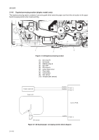
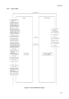
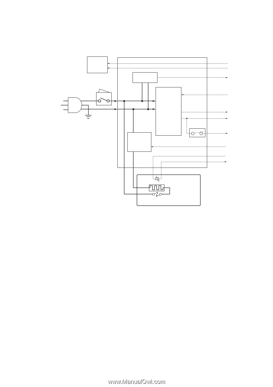
2-3 Operation of the PWBs 2-3-1 Power source PWB 2H5/2HS AC input Left cooling fan motor Power switch Power source PWB Zero cross signal circuit Switching regulator circuit +24V1 FAN ZCROSS SLEEP +5V1 Fuser heater lamp control circuit +24V2 Interlock switch HEATN +3.3V1 THERM Fuser unit Fuser thermistor Fuser heater lamp Fuser thermal cutout Figure 2-3-1 Power source PWB block diagram 2-3-1
-
 1
1 -
2
-
3
-
4
-
5
-
6
-
7
-
8
-
9
-
10
-
11
-
12
-
13
-
14
-
15
-
16
-
17
-
18
-
19
-
20
-
21
-
22
-
23
-
24
-
25
-
26
-
27
-
28
-
29
-
30
-
31
-
32
-
33
-
34
-
35
-
36
-
37
-
38
-
39
-
40
-
41
-
42
-
43
-
44
-
45
-
46
-
47
-
48
-
49
-
50
-
51
-
52
-
53
-
54
-
55
-
56
-
57
-
58
-
59
-
60
-
61
-
62
-
63
-
64
-
65
-
66
-
67
-
68
-
69
-
70
-
71
-
72
-
73
-
74
-
75
-
76
-
77
-
78
-
79
-
80
-
81
-
82
-
83
-
84
-
85
-
86
-
87
-
88
-
89
-
90
-
91
-
92
-
93
-
94
-
95
-
96
-
97
-
98
-
99
-
100
-
101
-
102
-
103
-
104
-
105
-
 106
106 -
 107
107 -
 108
108 -
 109
109 -
 110
110 -
 111
111 -
 112
112 -
 113
113 -
 114
114 -
 115
115 -
 116
116 -
117
-
118
-
119
-
120
-
121
-
122
-
123
-
124
 |
 |
2H5/2HS
2-3-1
2-3 Operation of the PWBs
2-3-1
Power source PWB
Figure 2-3-1 Power source PWB block diagram
+5V1
SLEEP
+24V1
+24V2
FAN
+3.3V1
ZCROSS
HEATN
THERM
Power source PWB
Left
cooling
fan motor
Fuser thermistor
Fuser thermal cutout
Fuser unit
Switching
regulator
circuit
Zero cross
signal circuit
AC input
Interlock
switch
Power switch
Fuser heater
lamp control
circuit
Fuser
heater lamp