Kyocera FS 1100 Service Manual - Page 112
Power source PWB silk-screen diagram, Connector, Signal, Voltage, Description, YC101
 |
View all Kyocera FS 1100 manuals
Add to My Manuals
Save this manual to your list of manuals |
Page 112 highlights
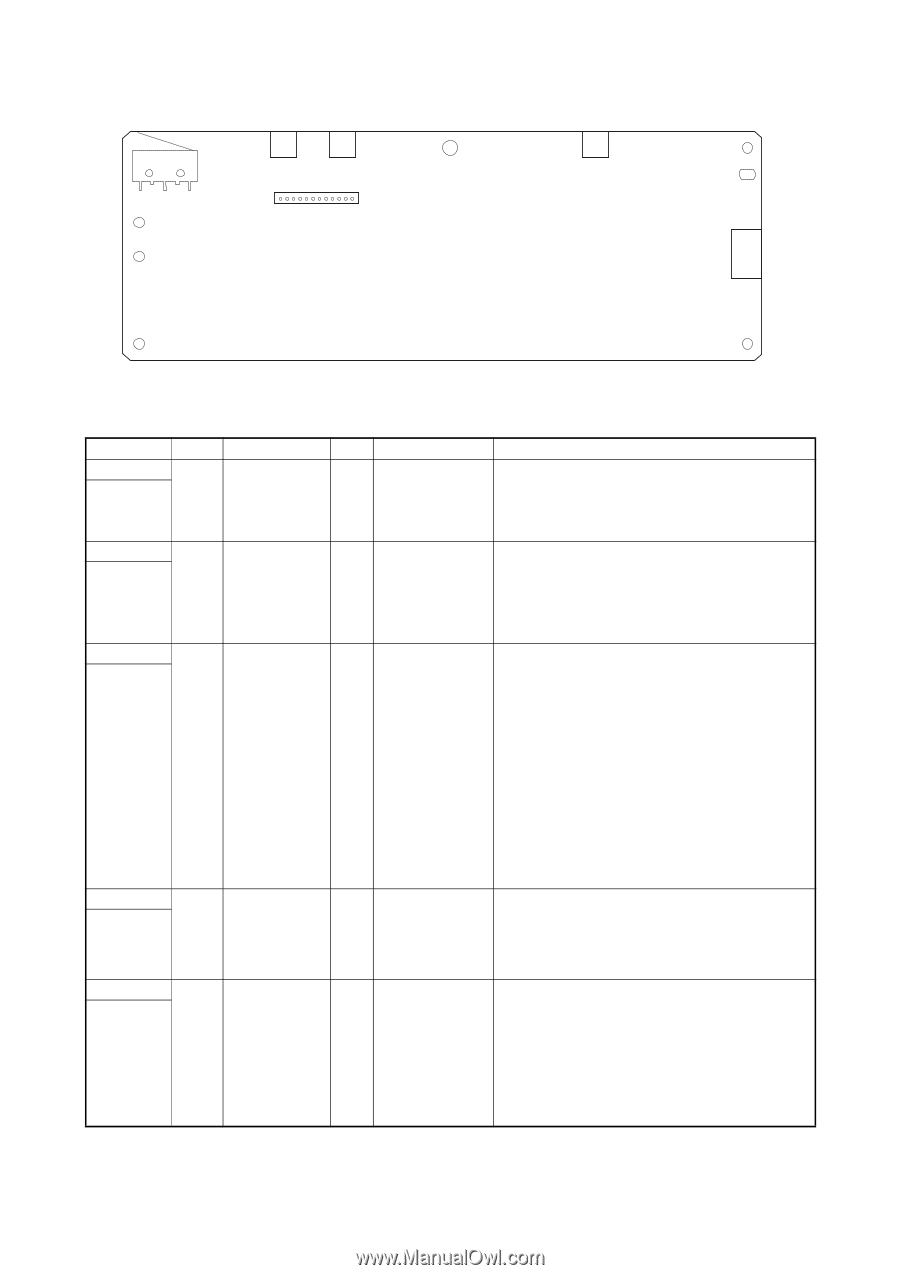
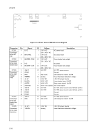
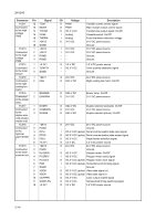
2H5/2HS YC104 YC105 YC103 YC102 YC101 Figure 2-3-2 Power source PWB silk-screen diagram Connector YC101 Connected to the AC inlet YC102 Connected to the fuser heater lamp YC103 Connected to the high voltage PWB YC104 Connected to the left cooling fan motor YC105 Connected to the fuser thermistor Pin Signal 1 LIVE 2 NEUTRAL 1 HEATER COM 2 N.C. 3 HEATER LIVE 1 +24V1 2 SGND 3 FAN 4 THERM 5 +3.3V 6 HEATN 7 SLEEP 8 ZCROSS 9 +24V2 10 +24V2 11 PGND 12 PGND 1 +24V1 2 FAN 1 +3.3V1 2 THERM I/O Voltage Description I 120 V AC AC power input 220 - 240 V AC I 120 V AC AC power input 220 - 240 V AC O 120 V AC Fuser heater lamp output 220 - 240 V AC -- Not used O 120 V AC Fuser heater lamp output 220 - 240 V AC O 24 V DC 24 V DC power source -- Ground I 0/24 V DC Left cooling fan motor: On/Off O Analog Fuser thermistor detection voltage I 3.3 V DC 3.3 V DC power source I 0/3.3 V DC Fuser heater lamp: On/Off I 0/3.3 V DC Sleep mode signal: On/Off O 0/3.3 V DC (pulse) Zero cross signal O 24 V DC 24 V DC power source (via interlock switch) O 24 V DC 24 V DC power source (via interlock switch) -- Ground -- Ground O 24 V DC 24 V DC power source O 0/24 V DC Left cooling fan motor: On/Off O 3.3 V DC I Analog 3.3 V DC power source Fuser thermistor detection voltage 2-3-2
-
 1
1 -
2
-
3
-
4
-
5
-
6
-
7
-
8
-
9
-
10
-
11
-
12
-
13
-
14
-
15
-
16
-
17
-
18
-
19
-
20
-
21
-
22
-
23
-
24
-
25
-
26
-
27
-
28
-
29
-
30
-
31
-
32
-
33
-
34
-
35
-
36
-
37
-
38
-
39
-
40
-
41
-
42
-
43
-
44
-
45
-
46
-
47
-
48
-
49
-
50
-
51
-
52
-
53
-
54
-
55
-
56
-
57
-
58
-
59
-
60
-
61
-
62
-
63
-
64
-
65
-
66
-
67
-
68
-
69
-
70
-
71
-
72
-
73
-
74
-
75
-
76
-
77
-
78
-
79
-
80
-
81
-
82
-
83
-
84
-
85
-
86
-
87
-
88
-
89
-
90
-
91
-
92
-
93
-
94
-
95
-
96
-
97
-
98
-
99
-
100
-
101
-
102
-
103
-
104
-
105
-
106
-
 107
107 -
 108
108 -
 109
109 -
 110
110 -
 111
111 -
 112
112 -
 113
113 -
 114
114 -
 115
115 -
 116
116 -
 117
117 -
118
-
119
-
120
-
121
-
122
-
123
-
124
 |
 |