Kyocera FS 1100 Service Manual - Page 99
Developing DLP screw B
 |
View all Kyocera FS 1100 manuals
Add to My Manuals
Save this manual to your list of manuals |
Page 99 highlights
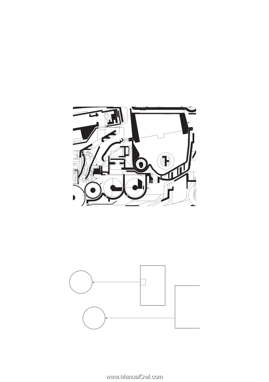
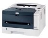
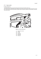
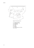
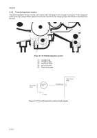
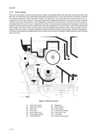
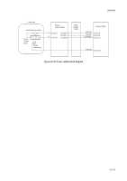
2H5/2HS 2-1-4 Developing section The latent image constituted on the drum is developed into a visible image. The developing roller contains a 3-pole (S-NS) magnet roller and an aluminum cylinder rotating around the magnet roller. Toner attracts to the magnet sleeve since it is powdery ink made of black resin bound to iron particles. Developing blade, magnetized by magnet, is positioned approximately 0.3 mm above the magnet sleeve to constitute a smooth layer of toner in accordance with the magnet sleeve revolution. The developing roller is applied with the AC-weighted, positive DC power source. Toner on the magnet sleeve is given a positive charge. The positively charged toner is then attracted to the areas of the drum which was exposed to the laser light. (The gap between the drum and the magnet sleeve is approximately 0.32 mm.) The non-exposed areas of the drum repel the positively charged toner as these areas maintain the positive charge. The developing roller is also AC-biased to ensure contrast in yielding by compensating the toner's attraction and repelling action during development. 8 3 4 1 7 2 6 5 Figure 2-1-14 Developing unit and toner container (1) Magnet sleeve (2) Magnet roller (3) Developing blade (4) Blade magnet (5) DLP screw A (6) DLP screw B (7) DLP case (8) Toner container High voltage PWB Developing roller Developing bias output B Magnet roller Magnet sleeve Developing clutch Control PWB DLPDRN YC308-6 Figure 2-1-15 Developing section block diagram 2-1-9
-
 1
1 -
2
-
3
-
4
-
5
-
6
-
7
-
8
-
9
-
10
-
11
-
12
-
13
-
14
-
15
-
16
-
17
-
18
-
19
-
20
-
21
-
22
-
23
-
24
-
25
-
26
-
27
-
28
-
29
-
30
-
31
-
32
-
33
-
34
-
35
-
36
-
37
-
38
-
39
-
40
-
41
-
42
-
43
-
44
-
45
-
46
-
47
-
48
-
49
-
50
-
51
-
52
-
53
-
54
-
55
-
56
-
57
-
58
-
59
-
60
-
61
-
62
-
63
-
64
-
65
-
66
-
67
-
68
-
69
-
70
-
71
-
72
-
73
-
74
-
75
-
76
-
77
-
78
-
79
-
80
-
81
-
82
-
83
-
84
-
85
-
86
-
87
-
88
-
89
-
90
-
91
-
92
-
93
-
 94
94 -
 95
95 -
 96
96 -
 97
97 -
 98
98 -
 99
99 -
 100
100 -
 101
101 -
 102
102 -
 103
103 -
 104
104 -
105
-
106
-
107
-
108
-
109
-
110
-
111
-
112
-
113
-
114
-
115
-
116
-
117
-
118
-
119
-
120
-
121
-
122
-
123
-
124
 |
 |