Kyocera FS 1100 Service Manual - Page 75
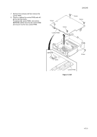
and refit all the removed parts.
 |
View all Kyocera FS 1100 manuals
Add to My Manuals
Save this manual to your list of manuals |
Page 75 highlights
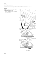
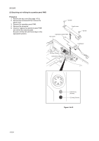
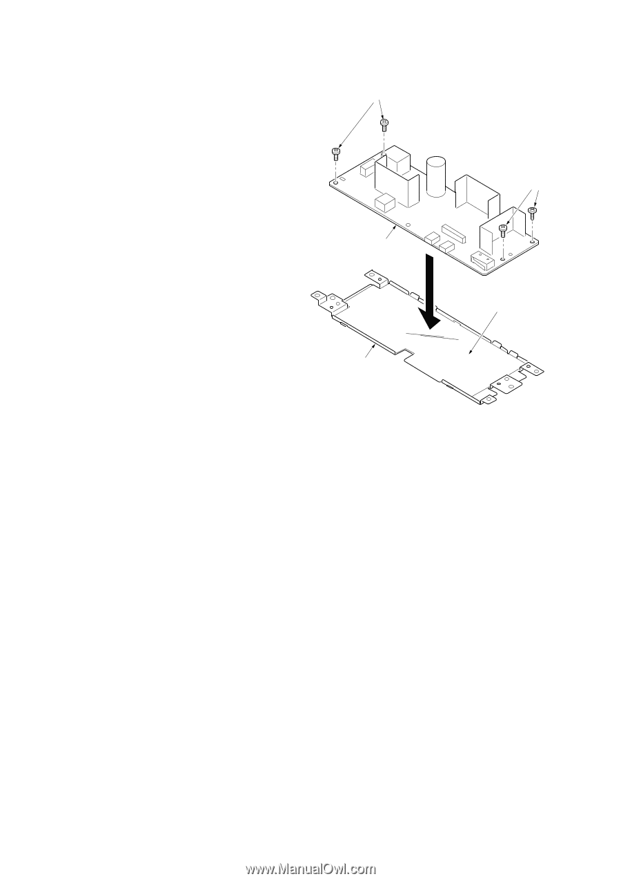
6. Remove four screws and then remove the power source plate from the power source PWB. 7. Check or replace the power source PWB and refit all the removed parts. Caution: The power source film must be installed in the specified position. Screws 2H5/2HS Screws Power source PWB Power source film Power source plate Figure 1-5-32 1-5-23
-
 1
1 -
2
-
3
-
4
-
5
-
6
-
7
-
8
-
9
-
10
-
11
-
12
-
13
-
14
-
15
-
16
-
17
-
18
-
19
-
20
-
21
-
22
-
23
-
24
-
25
-
26
-
27
-
28
-
29
-
30
-
31
-
32
-
33
-
34
-
35
-
36
-
37
-
38
-
39
-
40
-
41
-
42
-
43
-
44
-
45
-
46
-
47
-
48
-
49
-
50
-
51
-
52
-
53
-
54
-
55
-
56
-
57
-
58
-
59
-
60
-
61
-
62
-
63
-
64
-
65
-
66
-
67
-
68
-
69
-
 70
70 -
 71
71 -
 72
72 -
 73
73 -
 74
74 -
 75
75 -
 76
76 -
 77
77 -
 78
78 -
 79
79 -
 80
80 -
81
-
82
-
83
-
84
-
85
-
86
-
87
-
88
-
89
-
90
-
91
-
92
-
93
-
94
-
95
-
96
-
97
-
98
-
99
-
100
-
101
-
102
-
103
-
104
-
105
-
106
-
107
-
108
-
109
-
110
-
111
-
112
-
113
-
114
-
115
-
116
-
117
-
118
-
119
-
120
-
121
-
122
-
123
-
124
 |
 |
2H5/2HS
1-5-23
6.
Remove four screws and then remove the
power source plate from the power source
PWB.
7.
Check or replace the power source PWB
and refit all the removed parts.
Caution: The power source film must be
installed in the specified position.
Figure 1-5-32
Power source PWB
Screws
Screws
Power source plate
Power source film