LG LP070HED1 Service Manual - Page 16
Electrical Parts
 |
View all LG LP070HED1 manuals
Add to My Manuals
Save this manual to your list of manuals |
Page 16 highlights
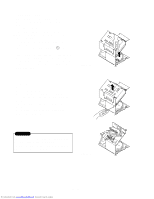
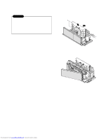
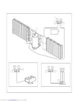
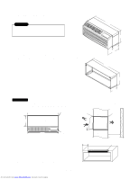
2.2.3 SHROUD 1. Remove the axial fan. (Refer to section 2.2.3) 2. Remove the 4 screws which fasten the condenser with the shroud and the basepan. 3. Remove the shroud. 4. Re-install the component by referring to the removal procedure. 2.3. ELECTRICAL PARTS 2.3.1 OUTDOOR MOTOR 1. Remove the clamp cord and disconnect a wire housing in control box. (Refer to section 2.1.2) 2. Remove the axial fan. (Refer to section 2.2.3) 3. Remove the 2 screws which fasten the motor. (See Figure 10) 4. Remove the motor 5. Re-install the component by referring to the removal procedure, above. 2.3.2 INDOOR MOTOR (Refer to section 2.2.2) 2.3.3 COMPRESSOR 1. Discharge the refrigerant system using a refrigerant recovery system. If there is no valve to attach the recovery system, install one (such as a WATCO A-1) before venting the refrigerant. Leave the valve in place after servicing the system. 2. Disconnect the 3 leads from the compressor. 3. After purging the unit completely, unbraze the suction and discharge tubes at the compressor connections. 4. Remove the 3 nuts and the 3 washers which fasten the compressor. (See Figure 11) 5. Remove the compressor. 6. Re-instill the components by referring to the removal procedure, above. 2.3.4 CAPACITOR 1. Remove the control box. (Refer to section 2.1.2) 2. Remove 1 screw and disconnect the leads which connected to the box type capacitor. (See Figure 12) 3. Remove 1 screw and the clamp which fastens the can-type capacitor. 4. Disconnect all the leads of capacitor terminals. 5. Re-install the components by referring to the removal procedure, above. Figure 9 Figure 10 Figure 11 Downloaded from www.Manualslib.com manuals search engine -16- Figure 12
-
 1
1 -
2
-
3
-
4
-
5
-
6
-
7
-
8
-
9
-
10
-
 11
11 -
 12
12 -
 13
13 -
 14
14 -
 15
15 -
 16
16 -
 17
17 -
 18
18 -
 19
19 -
 20
20 -
 21
21 -
22
-
23
-
24
-
25
-
26
-
27
-
28
-
29
-
30
-
31
-
32
-
33
-
34
-
35
-
36
-
37
-
38
-
39
-
40
-
41
-
42
-
43
-
44
-
45
-
46
-
47
-
48
-
49
-
50
-
51
-
52
-
53
-
54
-
55
-
56
-
57
-
58
-
59
 |
 |
