LG LP070HED1 Service Manual - Page 18
Refrigeration Cycle
 |
View all LG LP070HED1 manuals
Add to My Manuals
Save this manual to your list of manuals |
Page 18 highlights
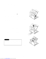
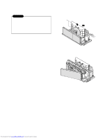
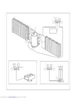
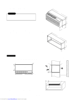
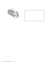
2.4 REFRIGERATION CYCLE CAUTION Discharge the refrigerant system using a refrigerant recovery system. If there is no valve to attach the recovery system, install one (such as a WATCO A-1) before venting the refrigerant. Leave the valve in place after servicing the system. 2.4.1 CONDENSER 1. Remove the brace and the shroud. (Refer to section 2.2.2) 2. Remove the 4 screws which fasten the shroud. (Refer to section 2.2.2) 3. Push forward the shroud and remove the 2 screws which fasten the condenser with the basepan. 4. After discharging the refrigerant completely, unbraze the interconnecting tube at the condenser connections. 5. Remove the condenser. 6. Re-install the components by referring to notes. (See Figure 15) 2.4.2 EVAPORATOR 1. Remove the front grille. (Refer to section 2.1.1) 2. Discharge the refrigerant completely. 3. Remove the control box assembly. (Refer to section 2.1.2) 4. Remove the 4 screws which fasten the evaporator at the left side and the right side. 5. Move the evaporator sideward carefully and then unbraze the interconnecting tube at the evaporator connectors. 6. Remove the evaporator. 7. Re-install the components by referring to notes. (See Figure 16) 2.4.3 CAPILLARY TUBE 1. After discharging the refrigerant completely, unbraze the interconnecting tube at the capillary tube. 2. Remove the capillary tube. 3. Re-install the components by referring to notes. Figure 15 Figure 156 Downloaded from www.Manualslib.com manuals search engine -18-
-
 1
1 -
2
-
3
-
4
-
5
-
6
-
7
-
8
-
9
-
10
-
11
-
12
-
 13
13 -
 14
14 -
 15
15 -
 16
16 -
 17
17 -
 18
18 -
 19
19 -
 20
20 -
 21
21 -
 22
22 -
 23
23 -
24
-
25
-
26
-
27
-
28
-
29
-
30
-
31
-
32
-
33
-
34
-
35
-
36
-
37
-
38
-
39
-
40
-
41
-
42
-
43
-
44
-
45
-
46
-
47
-
48
-
49
-
50
-
51
-
52
-
53
-
54
-
55
-
56
-
57
-
58
-
59
 |
 |
