LG LP070HED1 Service Manual - Page 31
Internal Condensate Removal Pump, Wiring
 |
View all LG LP070HED1 manuals
Add to My Manuals
Save this manual to your list of manuals |
Page 31 highlights
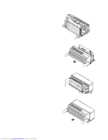
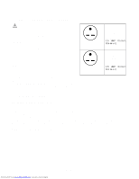
15. Place one of the hose clamps over one end of the 16-inch vinyl hose. Place the same end over the barbed discharge tube of the pump assembly. Place a hose clamp on the other end of the 16 inch hose. Place this same end over the shorter leg of the overflow tube and secure the hose with the hose clamp. (Figure 34) Figure 34 U Clip Plastic Grommet 18. To gain access inside the control panel, remove the knobs and escutcheon. Remove the two screws holding the panel in position. Tilt the control panel forward, being careful not to pinch any wires. (Figure 36) 19. Lift the control panel up so the control panel is free of its hinges. Position the control panel so there is easy access for mounting components to the control panel. (Figure 36) Figure 36 Mode Switch Thermostat Overflow Tube Remove two screws to gain access inside Control Panel Fuse Holder Knockouts under panel 16. Place a hose clamp over one end of the 11-inch long hose. Push this same end over the longer leg of the overflow tube and secure with the hose clamp. Place another hose clamp over the other end of the 11-inch hose. Push this same end over the condensate tube protruding out from the back of the partition panel and secure with the hose clamp. (Figure 34) 17. Route the condensate pump cord through the U clip on the condenser shroud, through the plastic grommet in the sheet metal condenser wing, through the plastic ring in the panel, and then through the hole in the panel where the compressor wires are routed through the panel. NOTE: The permagum may have to be removed to feed the wires through the panel, make sure wires have no slack and replace the permagum to prevent air leaks. (Figures 34 and 35) Figure 35 20. Connect the condensate pump to the ICR relay on the terminal board per Figure 37. 21. Install the basepan drain plug into the basepan drain hole by pushing it up into the drain hole from the bottom of the basepan. This will defeat the thermostatic controlled drain valve. The basepan drain is located to the left of the outside coil (as viewed from the back of the unit). Figure 37 - Internal Condensate Removal Pump Wiring Permagum Plastic Ring Grommet Condensate Pump Cord Downloaded from www.Manualslib.com manuals search engine -31-
-
 1
1 -
2
-
3
-
4
-
5
-
6
-
7
-
8
-
9
-
10
-
11
-
12
-
13
-
14
-
15
-
16
-
17
-
18
-
19
-
20
-
21
-
22
-
23
-
24
-
25
-
 26
26 -
 27
27 -
 28
28 -
 29
29 -
 30
30 -
 31
31 -
 32
32 -
 33
33 -
 34
34 -
 35
35 -
 36
36 -
37
-
38
-
39
-
40
-
41
-
42
-
43
-
44
-
45
-
46
-
47
-
48
-
49
-
50
-
51
-
52
-
53
-
54
-
55
-
56
-
57
-
58
-
59
 |
 |
