LG LP070HED1 Service Manual - Page 23
Preparation of the Wall Case for All Types
 |
View all LG LP070HED1 manuals
Add to My Manuals
Save this manual to your list of manuals |
Page 23 highlights
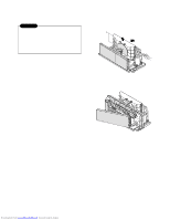
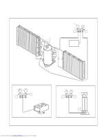
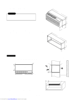
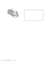
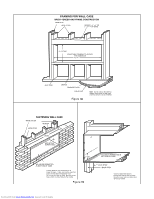
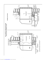
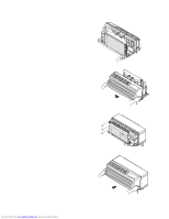
3.2.2 PREPARATION OF THE FRONT GRILLE Carefully remove shipping tape from the front grille. The outside edge of the wall case should extend at least 1/4" beyond the outside wall. This is necessary for proper caulking, to prevent sealing thedrain holes in the rear flange of the wall case, and to facilitate the installation of an accessory drain, if used. Shipping Tape Brick, Frame, Stucco and Shingle Construction For new construction, the opening for the wall case should be framed and the wall case inserted into the opening during construction. Lintels should be used when the building material is heavy and is not self supporting (such as brick). The wall case will fit an opening of six courses of standard brick or five courses of jumbo brick. Wall framing in this type construction is normally on 16" centers and the wall case will fit a framed opening spanning three 16" O.C. 2" x 4" stud spaces. For existing construction the indoor and outdoor wall will need to be cut out, allowing for clearances of 1/8" on all sides of the wall case. Work should begin on the inside wall. Cut the correct dimensions and mark (using drill holes) the outside wall from each corner of the inside cutout. Studding that interferes with the opening must be removed and a suitable frame constructed to secure the wall case and provide adequate support for case and chassis. Preparation of the Wall Case for All Types of Construction As shipped, the LG wall sleeve is ready for installation. Do not remove the stiffener from inside the wall case or the weather closure panel from the outside face of the wall case until the outdoor grille and chassis are ready to be installed. The wall case should be level from side to side and from level to 1/4 bubble tilt to the outdoors. The condensate disposal system in the unit is designed to dissipate the condensate water generated during cooling operation in accordance with ARI standards and actually uses this water for maximum unit efficiency. A level unit will also insure proper performance of the Internal Condensate Removal (ICR) system optional on heat pump units. 2. The wall case should be secured to the wall at both sides. Use a minimum of two screws or other fastening device on each side. See Figure 2 page 19. Mark the wall case on each side 2" from the bottom and 2" from the top at a point where basic wall structure is located. Drill wall case and use fasteners appropriate for wall construction. All holes for fasteners in the side of the wall case must be at least 2" up from the bottom of the wall case. Never locate screws or put other holes in the bottom of the wall case. If the wall opening is greater than the case dimensions, spacers must be used on the sides between the wall case and the wall support structure to prevent distorting the wall case. 3. Caulk or gasket the entire opening on the outside between the wall case and exterior wall surface (4 sides) to provide total water and air seal. 4. Caulk or gasket room-side opening between wall case and interior wall surface (4 sides). Opening beneath or around the wall case can allow outdoor air to leak into the room resulting in increased operating costs and improper room temperature control. Care should be taken in location of electrical supply entry in relationship to wall sleeve to assure access to receptacle or junction box once unit is installed. Installation of Wall Case in Wall Opening 1. Position the wall case into the wall. The room side edge of the wall case should be at least flush with the finished wall for line cord installations and permanent connection installations when no sub-base is used, and should project into the room at least 2-3/8" when a sub-base is used. If the minimum exterior dimensions are not met, refer to page 23. Downloaded from www.Manualslib.com manuals search engine -23-
-
 1
1 -
2
-
3
-
4
-
5
-
6
-
7
-
8
-
9
-
10
-
11
-
12
-
13
-
14
-
15
-
16
-
17
-
 18
18 -
 19
19 -
 20
20 -
 21
21 -
 22
22 -
 23
23 -
 24
24 -
 25
25 -
 26
26 -
 27
27 -
 28
28 -
29
-
30
-
31
-
32
-
33
-
34
-
35
-
36
-
37
-
38
-
39
-
40
-
41
-
42
-
43
-
44
-
45
-
46
-
47
-
48
-
49
-
50
-
51
-
52
-
53
-
54
-
55
-
56
-
57
-
58
-
59
 |
 |
