LG LP070HED1 Service Manual - Page 29
Condensate Disposal Pump Kit, Installation
 |
View all LG LP070HED1 manuals
Add to My Manuals
Save this manual to your list of manuals |
Page 29 highlights
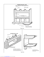
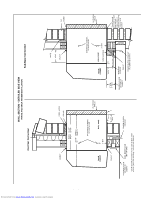
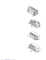
Condensate Disposal Pump Kit Installation Part No: AYSB3101 Description The internal condensate pump serves as a means for disposing of condensate generated during heat pump operation by transferring it to the indoor coil. The warm coil surface and the warm room air help in evaporation of the condensate while adding humidity to the room. As with any equipment of this type, the addition of this kit will decrease the effective heating capacity of the unit. This kit is not intended for use in seacoast or corrosive environments. 2. Unplug and remove the PTAC chassis from the wallsleeve. Move the chassis where the front and back of the chassis can be easily accessed. 3. Remove the top cover assembly, net steel.(Figure 27) Figure 27 NOTE: Under extreme high humidity conditions, the internal condensate pump may not be able to dispose of all the condensate produced, and condensate would then drip from the outside of the wall sleeve. If this condensation is unacceptable, then a drain system (including factory approved drain kit for the wall sleeve) should be installed. 4. Lift the heater/discharge deck assembly approximately 10 inches by unscrewing three screws (two on the left side, one on the right side of the discharge deck) holding the discharge deck to the chassis. Lift upward being careful not to pinch heater wires. (Figure 28) Receiving Upon receipt of the product, inspect the shipping carton for signs of visible damage. Report any damage or shortage to the carrier and note it on the delivery receipt. Unit must be stored in its original shipping carton in a dry, secure place prior to its installation and use. Figure 28 Mounting Screws Installation The installation and servicing of the equipment referred to in this booklet should be performed by qualified, experienced technicians. WARNING Hazardous Voltage! Disconnect all electric power, including remote disconnects before servicing. Follow proper lockout/tagout procedures to ensure the power can not be inadvertently energized. Failure to disconnect power before servicing could result in death or serious injury. Important Note: The unit OFF switch does not disconnect all electrical power to this unit. Condensate Tube 5. Place coil cover on top of the evaporator coil with flanges pointing down. Make sure cover is over entire top of coil. (Figure 28) 6. Position the short end of the condensate tube through the back wall of the partition panel using existing hole. The condensate tube should protrude through the partition panel by 1-3/4 inches. Rotate the condensate tube so the tube lays flat on the coil cover. (Figures 28 & 29) 1. Remove front by rotating bottom outward and then lifting up and out from chassis. -29- Downloaded from www.Manualslib.com manuals search engine
-
 1
1 -
2
-
3
-
4
-
5
-
6
-
7
-
8
-
9
-
10
-
11
-
12
-
13
-
14
-
15
-
16
-
17
-
18
-
19
-
20
-
21
-
22
-
23
-
 24
24 -
 25
25 -
 26
26 -
 27
27 -
 28
28 -
 29
29 -
 30
30 -
 31
31 -
 32
32 -
 33
33 -
 34
34 -
35
-
36
-
37
-
38
-
39
-
40
-
41
-
42
-
43
-
44
-
45
-
46
-
47
-
48
-
49
-
50
-
51
-
52
-
53
-
54
-
55
-
56
-
57
-
58
-
59
 |
 |
