Lenovo NetVista A22 User guide for NetVista 2254, 2256, 2257, 6336, 6337, 6339 - Page 27
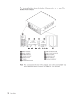
The following illustration shows the location of the connectors on the back of
 |
View all Lenovo NetVista A22 manuals
Add to My Manuals
Save this manual to your list of manuals |
Page 27 highlights
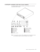
The following illustration shows the location of the connectors on the back of the microtower model computer. 1 Mouse connector 2 Keyboard connector 3 Serial connector 4 Parallel connector 5 Monitor connector 6 USB connectors 7 Ethernet connector 8 Audio line out connector 9 Audio line in connector 10 Microphone connector 11 Serial connector 12 PCI slots 13 Power connector Note: The connectors on the rear of the computer have color-coded icons to help you to determine where to connect the cables on your computer. Chapter 2. Installing external options 15
-
 1
1 -
2
-
3
-
4
-
5
-
6
-
7
-
8
-
9
-
10
-
11
-
12
-
13
-
14
-
15
-
16
-
17
-
18
-
19
-
20
-
21
-
 22
22 -
 23
23 -
 24
24 -
 25
25 -
 26
26 -
 27
27 -
 28
28 -
 29
29 -
 30
30 -
 31
31 -
 32
32 -
33
-
34
-
35
-
36
-
37
-
38
-
39
-
40
-
41
-
42
-
43
-
44
-
45
-
46
-
47
-
48
-
49
-
50
-
51
-
52
-
53
-
54
-
55
-
56
-
57
-
58
-
59
-
60
-
61
-
62
-
63
-
64
-
65
-
66
-
67
-
68
-
69
-
70
-
71
-
72
-
73
-
74
-
75
-
76
-
77
-
78
-
79
-
80
-
81
-
82
-
83
-
84
-
85
-
86
 |
 |
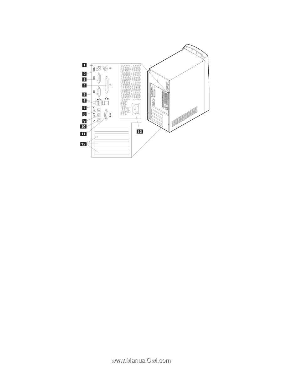
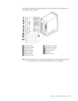
The following illustration shows the location of the connectors on the back of the
microtower model computer.
±1²
Mouse connector
±8²
Audio line out connector
±2²
Keyboard connector
±9²
Audio line in connector
±3²
Serial connector
±10²
Microphone connector
±4²
Parallel connector
±11²
Serial connector
±5²
Monitor connector
±12²
PCI slots
±6²
USB connectors
±13²
Power connector
±7²
Ethernet connector
Note:
The connectors on the rear of the computer have color-coded icons to help
you to determine where to connect the cables on your computer.
Chapter 2. Installing external options
15