Lenovo NetVista A22 User guide for NetVista 2254, 2256, 2257, 6336, 6337, 6339 - Page 43
Installing memory, DIMM heights of 38.1 mm 1.5 inches
 |
View all Lenovo NetVista A22 manuals
Add to My Manuals
Save this manual to your list of manuals |
Page 43 highlights
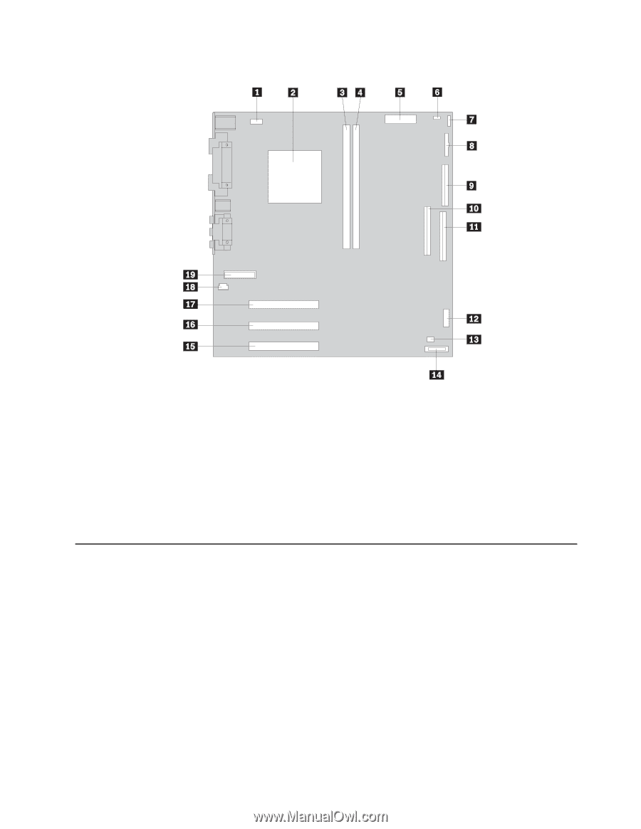
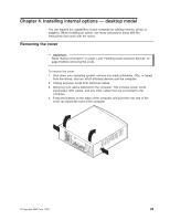
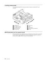
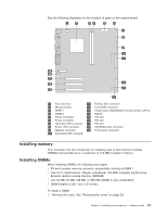
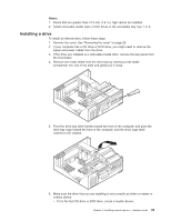
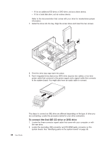
See the following illustration for the location of parts on the system board. 1 Fan connector 11 2 Microprocessor 12 3 DIMM 1 13 4 DIMM 2 14 5 Power connector 15 6 Power connector 16 7 Hard disk LED connector 17 8 Power LED connector 18 9 Diskette connector 19 10 Secondary IDE connector Primary IDE connector Front USB connector Virtual Clear CMOS/BIOS recovery jumper (JP14) Battery PCI slot PCI slot PCI slot CD-ROM audio connector Front panel connector Installing memory Your computer has two connectors for installing dual in-line memory modules (DIMMs) that provide up to a maximum of 512 MB of system memory. Installing DIMMs When installing DIMMs, the following rules apply: v Fill each system memory connector sequentially, starting at DIMM 1 v Use 3.3 V, synchronous, 168-pin, unbuffered, 133 MHz nonparity synchronous dynamic random access memory (SDRAM) v Use 32 MB, 64 MB, 128 MB, or 256 MB DIMMs in any combination v DIMM heights of 38.1 mm (1.5 inches) To install a DIMM: 1. Remove the cover. See "Removing the cover" on page 29. Chapter 4. Installing internal options - desktop model 31
-
 1
1 -
2
-
3
-
4
-
5
-
6
-
7
-
8
-
9
-
10
-
11
-
12
-
13
-
14
-
15
-
16
-
17
-
18
-
19
-
20
-
21
-
22
-
23
-
24
-
25
-
26
-
27
-
28
-
29
-
30
-
31
-
32
-
33
-
34
-
35
-
36
-
37
-
 38
38 -
 39
39 -
 40
40 -
 41
41 -
 42
42 -
 43
43 -
 44
44 -
 45
45 -
 46
46 -
 47
47 -
 48
48 -
49
-
50
-
51
-
52
-
53
-
54
-
55
-
56
-
57
-
58
-
59
-
60
-
61
-
62
-
63
-
64
-
65
-
66
-
67
-
68
-
69
-
70
-
71
-
72
-
73
-
74
-
75
-
76
-
77
-
78
-
79
-
80
-
81
-
82
-
83
-
84
-
85
-
86
 |
 |